Pipe and Tubular Products of Steel
Pipe and Tubular Products of Steel
The term pipe and tubular product of steel is the used to cover all hollow products of steel. These products are normally produced in cylindrical shape. However, they are frequently altered by different processing methods to produce square, oval, rectangular, and other symmetrical forms. Pipe and tubular products have a large number of applications, but they are most commonly used for conveying of fluids and as structural members. Steel pipe and tubular products are normally produced from wrought carbon (C) or alloy constructional steels and are usually designated by the terms pipe, specialty tubing, and oil country tubular goods (OCTG) etc. Pipes and tubular products have an outside dimension, an inside dimension and the wall thickness as shown in Fig 1.
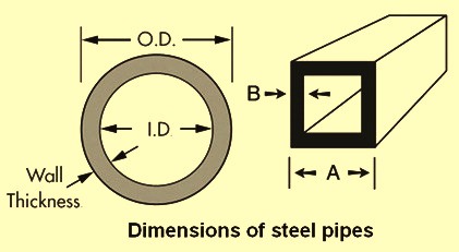
Fig 1 Dimensions of pipe and tubular products
The steel pipe and tubular products are usually classified broadly as (i) pipe, and (ii) tube. The application of the terms pipe and tube is not always consistent. The term pipe is normally used to describe cylindrical products made to standard combinations of outside diameter and wall thickness. The main difference between a pipe and a tube is the way the diameter of the pipe or tube is designated. Pipe is normally designated by a “Nominal Pipe Size” based upon the ID (inside diameter) of the most common wall thickness while the tube is designated by the measured OD (outside diameter). As an example a 20 mm steel pipe with 4 mm thickness has an OD of 28 mm while a 20 mm steel tube has an OD of 20mm.
The two broad classifications of steel pipe and tubular products are subdivided into several named use groups. As an example, the term tube covers three such groups namely (i) pressure tubes, (ii) structural tubing, and (iii) mechanical tubing. Similarly the term pipe covers five such groups, namely (i) standard pipe, (ii) line pipe, (iii) OCTG, (iv) water well pipe, and (v) pressure pipe. There are also pipes for special applications, such as conduit pipe and tubular piling which do not fit any of these classifications. These use groups have in turn a number of uses or named use subdivisions. Examples are oil and gas transmission pipes, water main pipe, drill pipe, casing pipe etc. These names have been developed without regard to method of manufacture, size range, wall thickness, or degree of finish.
Structural and mechanical tubing do not follow this system of nomenclature. In its place, their names are derived from the method of fabrication and degree of finish, such as cold formed welded or seamless hot finished.
Pipe and tubular products of steel can be made by forming a flat skelp, sheet, strip, or plate into a hollow cylinder and welding the resulting longitudinal or spiral seam together or by generating an opening in a solid cylinder by piercing and elongating the resultant hollow cylinder. The first group of products is called welded pipes, and the second group of products is called seamless pipes. The processes for producing these products are briefly described below.
Welding processes for pipe and tubular products
For the manufacture of welded pipe and tubular products of steel, flat rolled skelp, strip, sheet, or plate is formed into cylinders that are then joined at the longitudinal or spiral seam by one of the following processes.
- Electric resistance welding – The process consists of a series of steps. In the first step, the flat rolled steel is cold shaped into pipe form. Welding is done by the application of pressure and heat is generated by induction or by an electric current through the seam. The welding pressure is generated by constricting rolls and the electromagnetic effects of the high welding current. Electric resistance welded (ERW) pipe and tubular products having longitudinal seams are normally produced in sizes ranging from 3.2 mm nominal to 600 mm actual OD, but larger sizes are also obtainable. Electric resistance methods are also sometimes used for making pipe and tubular products by spiral welding. This method is normally used for the large diameter products.
- Continuous welding -In continuous (or furnace butt) welding process, skelp with square or slightly beveled edges is furnace heated to the welding temperature. The heated stock is roll formed into cylindrical shape as it emerges from the furnace. Additional heat is generally provided by an oxygen (O2) or air jet impinging on the seam edges, and the pipe passes through constricting rolls where the seam edges are welded by the pressure of the rolls. Continuous welded pipe and tubular products are available in nominal diameters from 3.2 mm to 100 mm.
- Fusion welding -In fusion welding process, the flat rolled steel, with suitably prepared edges , is formed into pipe shape by either hot or cold shaping. The flat rolled steel can be shaped longitudinally (straight seam) or bent into helical form (spiral welded). The edges are welded with or without simultaneously depositing filler metal in a molten or molten and vapour state. Mechanical pressure is not needed for welding. Fusion is generally accomplished by either electric arc or gas heating, or a combination of both. The upper limit of OD is determined mainly by the forming method and the fusion welding process used.
- Submerged arc welding – This process is a special method of shielded arc welding (SAW) in which the seam is submerged under a solid flux while being welded. The weld is made in two passes, one from inside the pipe and the other from outside the pipe, with around half the wall thickness being welded during each pass. The maximum diameter is limited by the capability of the forming equipment. Double submerged arc welded pipes are normally produced in OD of up to 3000 mm.
Seamless processes for pipe and tubular products
Pipe and tubular products of steel are manufactured by the following seamless processes. These products are produced up to 1200 mm by hot extrusion method and in diameters up to 2000 mm by the rotary piercing method.
- Hot extrusion method – This method is a hot working process for making hollows, suitable for processing into finished pipes of regular and irregular form, by forcing hot, pre-pierced billets through a suitably shaped orifice formed by an external die and internal mandrel. The outside of the hollow attains the size and contour imposed by the die while the inside conforms to the size and contour of the mandrel. Extruded hollows can be further worked into pipe and tubular products by cold finishing methods.
- Rotary piercing method -In the rotary piercing method, steel rounds of the required diameter and length are first heated to rolling temperature. The hot round is then fed into a set of rolls having crossed axes and surface contours which pull the round through the rolls, thus rupturing it longitudinally. The force of the rolls then causes the metal to flow around a piercing point, enlarging the axial hole, smoothing the inside surface, and forming a pipe. After being pierced, the rough pipe is usually hot rolled to final dimensions by means of plug mill or mandrel mill, which is usually followed by stretch reducing mill.
- Cupping and drawing method – In the cupping and drawing method a circular sheet or plate is hot cupped in a press through several pairs of conical dies, each successive pair being deeper and more nearly cylindrical than the previous set. The rough pipe then is drawn to the finished size.
Cold finishing
Both seamless and welded pipe and tubular products of suitable sizes can be cold finished. The cold finishing process can be used to increase or decrease the diameter, to produce shapes other than round, to produce a smoother surface or closer dimensional tolerances, or to modify mechanical properties. The most frequently used cold finishing process is cold drawing, in which the descaled hot worked pipe is plastically deformed by drawing it through a die and over a mandrel (mandrel drawing) to work both exterior and interior surfaces. Cold drawing through the die only (without a mandrel) is called sink drawing or sinking.
In pipe reducing by rotorolling or pilgering and in swaging, a reducing die works the pipe hollow over a mandrel. However, swaging can be done without a mandrel. The commercial significance of pipe reducing is that (i) very heavy reductions (up to 85 %) can be applied to mill length pipes, and (ii) the process can be applied to the refractory alloys that are difficult to cold draw because of high power requirements.
Pipe and tubular products of circular cross section can be cold finished on the outside by turning, grinding, or polishing, or by any combination of these processes. They may be bored, skived, or honed on the inside diameter. Since these operations involve stock removal only, with negligible plastic deformation, there is no enhancement of mechanical properties of these products.
Many of the standard specifications of pipe and tubular products involving strength are based on the properties of hot rolled or cold worked materials. Some high strength OCTG are heat treated to achieve the combination of high strength, ductility, and sulphide stress corrosion cracking (SSCC) resistance required by the intended application. Cold drawing can be employed to increase the strength and to improve the surface finish and dimensional accuracy of the these products. In some specifications the prescribed strength levels can best be achieved by cold working.
Pipe specifications and sizes
Pipes are distinguished from tubes by the fact that they are produced in relatively few sizes and, hence, in comparatively large quantities of each size. On the other hand, tubes are frequently made to custom sizes and may often have a large number of specific sizes and tolerances than pipes. Size of pipe is designated according to one of the two methods described here. Pipe less than 50 mm in diameter has a nominal or named size roughly equal to the ID of standard weight pipe. The OD of each size is standard, irrespective of its weight, in order to allow the use of standard thread sizes. Hence, the increase in wall thickness necessary to produce extra strong and double extra strong weights results in a decrease in the ID of the pipe. The size designation, however, remains the same as for standard weight pipe of the same OD. In case of pipes with the diameters of 50 mm and larger the pipe size is normally designated by OD, wall thickness, and weight per unit length. The size of OCTG is always designated by OD. Various pipe standards provide the standardized sizes and weights of pipes for the major named uses.
The situation with respect to the composition and strength required for the various end-uses can be summarized as described here. The simplest specification for pipe covers material which is produced for all ordinary purposes such as conveying fluids under low pressure, that may be bent, coiled, or flanged. Chemical composition is specified, and strength requirements consist of a tension test in addition to the hydrostatic test or optional nondestructive test (NDT) for seamless pipe. The chemical composition limits normally given in the standards for C and alloy steel pipes. The strength requirements are based on as-rolled material in the common qualities, with the classes being graded upward to annealed, normalized, normalized and tempered, or quenched and tempered properties for the higher qualities. Since ductility is considered desirable at higher strength levels, C content is restricted. To achieve such strength levels, alloying elements can be added or heat treatment can be given. When welding is to be used as a method of joining, there is additional reason for C restriction.
Common types of pipes
The following are the brief descriptions concerning the end uses of some of the common types of pipes.
- Standard pipe – It is standard weight, extra strong, and double extra strong welded or seamless pipe of ordinary finish and dimensional tolerances, produced in sizes up to 650 mm in nominal diameter, inclusive. This pipe is used for fluid conveyance and some structural purposes.
- Conduit pipe – It is welded or seamless pipe intended especially for fabrication into rigid conduit, a product used for the protection of electrical wiring systems. Conduit pipe is not subjected to hydrostatic testing unless so specified. It can be black or galvanized, as specified. It is furnished in standard weight pipe sizes from 6 mm to 150 mm in lengths of around 3 m to 6 m, with plain ends or threaded ends, as specified.
- Piling pipe – It is welded or seamless pipe for use as piles, with the cylinder section acting as a permanent load carrying member or as a shell to form cast-in-place concrete piles. There are normally three grades, which have different minimum tensile strengths, a variety of diameters, ranging from 150 mm to 600 mm, and a variety of wall thicknesses. Ends can be plain or beveled for welding.
- Pipe for nipples – It is standard weight, extra strong, or double extra strong welded or seamless pipe, produced for the manufacture of pipe nipples. Pipe for nipples is generally produced in random lengths with plain ends, in nominal sizes from 3 mm to 300 mm. Close outside diameter tolerances, sound welds, good threading properties, and surface cleanliness are necessary in the pipes used for nipples. Pipe for OCTG couplings is to be manufactured from seamless pipe. It is usually coated with oil or zinc (Zn) and is well protected before dispatch.
- Transmission or line pipe – It is welded or seamless pipe presently produced in sizes ranging from 3 mm nominal to 1200 mm actual OD and is used principally for conveying gas or oil. Transmission pipe is produced with ends plain, threaded, beveled, grooved, flanged, or expanded, as required for various types of mechanical couplings or for welded joints. When threaded ends and couplings are required, recessed couplings are used.
- Water main pipe – It is welded or seamless steel pipe used for conveying water for municipal and industrial purposes. Pipe lines for such purposes are usually designated as flow mains, transmission mains, force mains, water mains, or distribution mains. The mains are generally laid underground. Sizes of this pipe range from 40 mm to 2500 mm in nominal diameter in a variety of wall thicknesses. Pipe is produced with ends suitably prepared for mechanical couplings, with plain ends beveled for welding, or with bell and spigot joints for field connection. Pipe is produced in double random lengths of around 12 m, single random lengths of around 6 m, or in specified lengths. When required, it is produced with a specified coating or lining, or both.
- Oil country tubular goods – OCTG is a collective term applied in the oil and gas industries to three kinds of pipes used in oil wells namely (i) drill pipe, (ii) casing, and (iii) tubing. These products conform to respective standard specifications. The chemical composition requirements and the strength requirements are given in the respective standards. Drill pipe is used to transmit power by rotary motion from ground level to a rotary drilling tool below the surface and to convey flushing media to the cutting face of the tool. Drill pipe is produced in sizes ranging from 60 mm to 170 mm in OD. Size designations refer to actual OD and weight per metre. Drill pipe is usually upset, either internally or externally, or both, and is prepared to accommodate welded-on types of joints. Casing is used as a structural retainer for the walls of oil or gas wells, to exclude undesirable fluids and to confine and conduct oil or gas from productive subsurface strata to ground level. Casing is produced in sizes from 110 mm to 500 mm in OD. Size designations refer to actual OD and weight per metre. Ends are generally threaded and furnished with couplings, but can be prepared to accommodate other types of joints. Tube is used within the casing of oil wells to conduct oil and gas to ground level. It is produced in sizes from 25 mm to 115 mm in OD, in several weights per meter. Ends are threaded for special integral type joints or fitted with couplings and may or may not be upset externally.
- Water well pipe – It is a collective term applied for four types of pipes which are used in water wells. These are (i) drive pipe, (ii) reamed and drifted pipe, (iii) driven well pipe, and (iv) casing pipe. The chemical composition and strength requirements are given in the standards for these pipes. Drive pipe is used to transmit power from ground level to a rotary drill tool below the surface and to convey flushing media to the cutting face of the tool. The lengths of pipe have specially threaded ends that permit the lengths to butt inside the coupling. Drive pipe is produced in nominal sizes of 150 mm, 200 mm, 300 mm, 350 mm, and 400 mm in OD. Driven well pipe is threaded pipe in short lengths used for the manual driving of a drill tool or for use with short rigs. It is normally used in random lengths ranging from 0.9 m to 1.8 m or in random lengths ranging from 1.8 m to 3.0 m. Casing is used both to confine and conduct water to ground level and as a structural retainer for the walls of water wells. It is produced as threaded pipe in random lengths ranging from 5 m to 6.5 m and in sizes from 90 mm to 220 mm in OD. In water well practice in some countries, welded strings are sometimes used. Reseamed and drifted pipe is similar to casing, but is produced and inspected in a way which assures the well driller that the pipe string has a predetermined minimum diameter sufficient to permit unrestricted passage of pumps or other equipment through the string. The pipe is threaded and is produced in a wider range of sizes ranging from 25 mm to 300 mm in OD as compared to standard water well casing.
- Pressure pipe – Pressure pipe, as distinguished from pressure tubes, is a commercial term for pipe that is used to convey fluids at higher pressure or higher temperature, or both, but which is not subjected to the external application of heat. This product is not differentiated from other types of pipes by standards, and the applicable specifications are listed with the other types of pipes. Pressure pipe ranges in size from 3 mm nominal to 650 mm actual OD in different wall thicknesses. Pressure pipe is supplied in random lengths, with threaded or plain ends, as required.
- Pressure tubes – Pressure tubes are given a separate classification by both the standards and the manufacturers. The chemical composition limits for C steel and for alloy steel as well as the strength requirements are covered in the standards for these tubes. Pressure tubes are distinguished from pressure pipes in that they are suitable for the application of external heat while conveying pressurized fluids. Pressure tubes are used in different components of the boilers. These tubes are produced to actual OD and minimum or average wall thickness (as specified by the user) and can be hot finished or cold finished, as needed.
- Double wall brazed tubes – These are specialty tubes which are confined to small sizes. They are used in large quantities by the automotive industry for brake lines and fuel lines, and by the refrigeration industry for refrigerant lines. They are made by forming copper (Cu) coated strip into a tubular section with double walls, using either single strip or double strip construction. The tubes are then heated in a reducing atmosphere to join all mating surfaces completely. The resulting products are thus Cu coated both inside and outside. When required by the intended service, a tin (Sn) coated tubes can also be produced. Available sizes range from 3 mm to 15 mm in OD with wall thickness from 0.65 mm for 3 mm OD to 0.9 mm for 15 mm OD. These tubes are usually made to very small sizes for use with standard compression fittings. It can be sink drawn for the improvement of surface finish and tolerances.
- Structural tubes – Structural tube is used for the welded, riveted, or bolted construction of bridges and buildings and for general structural purposes. It is available as round, square, rectangular, or special shape tube, as well as tapered tube. These products are covered by relevant standards. Structural tube is produced with a maximum wall thickness of 13 mm and with maximum circumferences of 810 mm for seamless tubes and 1220 mm for welded tubes. The chemical composition limits and strength requirements are given in the relevant standards.
- Mechanical tubular product – Mechanical tubular product includes welded and seamless tubes used for a wide variety of mechanical purposes. It is usually produced to meet specific end-use requirements and therefore is produced in many shapes, to a variety of chemical compositions and mechanical properties, and with hot rolled or cold finished surfaces. Most of the mechanical tubes are available as per specifications of various standards. Mechanical tube is not produced to specified standard sizes, but it is produced to specified dimensions, which can be anything which the customer needs within the limits of production equipment or processes. Controlling tolerances are placed on the OD and wall thickness for hot finished tube and on OD, ID, and wall thickness for cold finished tube. Size is generally expressed in mm. Specifications for size includes any two of the controlling dimensions namely OD, ID, and wall thickness, but never all three. The chemical compositions normally available in mechanical tubes cover a wide variety of standard grades. In addition to the standard grades, several high strength low alloy (HSLA) grades and unique chemistries are produced to customer specifications. When the steel used, either C or alloy steel, requires normalizing or annealing after welding, such operations become a part of the specification. For example, a type of welded structural tubing made from C steel with nominal C content of 0.50 % is normally normalized.
- Welded mechanical tubular product – It is usually made mostly by electric resistance welding, but some is made by the various fusion welding processes. In all cases, the exterior welding flash can be removed (if needed) by cutting, grinding, or hammering. ERW mechanical tube is made from hot rolled or cold rolled C steel or from alloy steel strip. The welded tube is normally supplied as-welded, hot finished, or cold finished. Hot finishing operations usually consist of either a stretch reducing mill or a hot reducing mill (hot sinking). Microstructural and hardness variations associated with the welding are modified by either seam annealing the weld zone or full body normalizing the entire tube. Sizes of ERW mechanical tube in OD ranges from 6 mm to 400 mm and in wall thickness from 1.6 mm to 17 mm for hot rolled steel and 0.6 mm to 4.0 mm for cold rolled steel. Stretch reducing mills realize tube elongation, reduction in diameter, and control of wall thickness on very long mill lengths in essentially a continuous process. Walls as thick as 18 mm are produced within limited OD ranges.
- Continuous-welded cold-finished mechanical tubular product – It is the tube which has been hot formed by furnace butt welding and cold finished. It is furnished sink drawn or mandrel drawn and is available in OD ranging from up to 90 mm and wall thicknesses from 0.9 mm to 13 mm. The material is low C steel, and the product is, in effect, a form of cold-drawn pipe. Although supplied in a narrower size range than ERW tubes, it has two advantages which are (i) within the available size range, heavier walls are available, and (ii) there is no problem with flash.
- Seamless mechanical tubular product – It is available both hot and cold finished and in a wide variety of finishes and mechanical properties. It is made from C and alloy steels in sizes up to and including 325 mm in OD. Hot finished seamless tube is produced by rotary piercing or extrusion processes. Therefore, it has surfaces similar to the surface regularly produced on hot-rolled steel and, in general, cannot be held to dimensional tolerances as close as those of tubes produced by cold finishing. It is produced in sizes as small as 40 mm in OD. Cold finished mechanical tube can be produced by means of surface removal or by cold working. Surface removal includes turning, polishing, grinding, or machining. Cold working involves cold reducing to effect changes in cross sectional dimensions. Drawing over a mandrel is the most common method of cold working of the mechanical tube. Tube is prepared for drawing by first pointing it. The end of the tube is mechanically reduced in OD to allow the end to pass through the die for gripping. Tube is required to be pickled and lubricated before drawing. Pickling is typically accomplished by hydrochloric or sulphuric acid immersion. A subsequent phosphate immersion coating on the steel surface acts as a binder for the soap like lubricant. Complete coverage of both the ID and OD is needed to prevent galling and chatter during drawing. Reductions in cross-sectional area of 10 % to 30 % are normal. Drawing is usually followed by a thermal treatment, straightening, and non-destructive inspection. Cold working and surface removal are used primarily for the purpose of obtaining smaller OD, better finishes, thinner walls, and closer dimensional accuracy than is possible in hot finished tubes. In addition, cold worked tube offers improved mechanical properties and machinability. Cold working can also be used to produce tubes having cross sectional shapes other than round. Cold drawn tube are produced in the as drawn, cold worked condition, or thermally treated to the desired combination of mechanical properties or microstructure. Typical thermal treatments available are stress relief annealed, soft annealed, normalized, or quenched and tempered.
- Square, rectangular, and special shape sections- These are produced in welded or seamless tubes, starting with either round tube of the required diameter and wall thickness or square, unwelded tube. Squaring is done in a Turk’s head or by other cold working methods. A Turk’s head consists of a frame in which are mounted four rolls with their axes at 90 deg and adjusted so that the roll surfaces form an opening of the same shape as the section to be formed. The Turk’s head is mounted on a draw bench, and the round tubes are passed through the rolls in the same manner as they are passed through dies. When Turk’s head shaping does not provide close enough tolerances on either the outside or inside of uniformly rounded corners, or close enough diagonal dimensions, the forming is customarily accomplished by means of die-and-mandrel shaping. The corners of sections processed by this means are around 90 deg arcs and have greater uniformity throughout than is provided by Turk’s head shaping. Sections that can be processed in this manner are somewhat limited with regards to diameter, wall thickness, and outside and inside corner radii. In addition to providing square and rectangular tubes, many manufacturers of welded or seamless tube supply a variety of special sections, such as oval, streamline, hexagonal, octagonal, round inside and hexagonal or octagonal outside, ribbed inside or outside, triangular, round ended rectangular, and D-shape. Available manufacturing equipment limits the size range and sections available from the various manufacturers. These special sections can be made by passing round tube through Turk’s head rolls or through a die with or without the use of a mandrel.

Leave a Comment