Gears and their types
Gears and their types
Steel plant supplies material for the manufacture of gears and it uses gears of different types and sizes in the equipment and machineries deployed for the production of steel.
Gears are the most common means used for power transmission. They are compact, positive-engagement, power transmission elements that determine the speed, torque, and direction of rotation of driven machine elements. They are widely used in various mechanisms and devices to transmit power and motion positively (without slip) between two shafts which are (i) parallel, (ii) collinear, (iii) perpendicular and intersecting, (iv) perpendicular and nonintersecting, and (v) inclined at any arbitrary angle. The power transmission can be (i) without change in the direction of rotation, (ii) with change in the direction of rotation, (iii) without change of speed (of rotation), and (iv) with change in speed at any desired ratio. Sometimes a gearing system (rack – and – pinion) is used to transform rotary motion into linear motion and vice-versa.
Gear wheels have projections called teeth that are designed to intersect the teeth of another gear. When gear teeth fit together or interlock in this manner they are said to be in mesh. Gears in mesh are capable of transmitting force and motion alternately from one gear to another. The gear transmitting the force or motion is called the drive gear and the gear connected to the drive gear is called the driven gear.
Basically gears are wheels having, on its periphery, equispaced teeth which are so designed that those wheels transmit, without slip, rotary motion smoothly and uniformly with minimum friction and wear at the mating tooth profiles. For the achievement of such favourable conditions, maximum numbers of gears have their tooth form based on involute curve. Involute curve is simply defined as the locus of a point on a straight line which is rolled on the periphery of a circle or the locus of the end point of a stretched string while it is unwinding over a cylinder.
The diametral pitch describes the gear tooth size. It can be measured in teeth per inch or teeth per centimeter, but conventionally the diametral pitch is expressed as the number of teeth per inch of pitch diameter. Larger gears have fewer teeth per inch of diametral pitch. Another way of saying this is that gear teeth size varies inversely with diametral pitch.
The pitch diameter refers to the diameter of the pitch circle. If the gear pitch is known then the pitch diameter is easily calculated. Pitch diameter is the number of teeth on the gear divided by the diametral pitch (gear size). The pitch diameter is used to generate the pitch circle.
The pitch circle is the geometrical starting point for designing gears and gear trains. Gear trains refer to systems of two or more meshing gears. The pitch circle is an imaginary circle that contacts the pitch circle of any other gear with which it is in mesh. The pitch circle centers are used to ensure accurate center-to-center spacing of the meshing gears.
Backlash refers to the distance from the back of the drive gear tooth to the front of driven gear tooth of gears mated on the pitch circle. Standard gears are designed with a specified amount of backlash to prevent noise and excessive friction and heating of the gear teeth.
Pressure angle is the complement of the angle between the direction that the teeth exert force on each other, and the line joining the centers of the two gears. For involute gears, the teeth always exert force along the line of action, which, for involute gears, is a straight line. Thus, for involute gears, the pressure angle is constant.
Gears of the same pitch, but differing numbers of teeth can be paired to obtain a wide range of gear ratios. Gear ratios are used to increase mechanical advantage (torque) or increase rotational speed or velocity. The ratio of a given pair of spur gears is calculated by dividing the number of teeth on the driven gear, by the number of teeth on the drive gear. The ratio describes the drive gear revolutions needed to turn the driven gear one complete revolution. Gear ratio increases/decreases the torque of the driven gear by factor equal to the gear ratio but reduces/increases the velocity or rpm of the driven gear by the same amount.
Velocity refers to the rotational speed of a gear and can be expressed using a variety of units. Gear velocity is usually given in inches per minute. The gear industry often uses feet per minute. Velocity is expressed as the distance a point along the circumference of the pitch circle will travel over a given unit of time. Velocity can be calculated by multiplying pitch circle circumference with the rpm (revolutions per minute).
Types of gears and their characteristics
Gears are normally classified in three ways. The classification of gears is mainly (i) as per the configuration, (ii) as per the pattern of motion, and (iii) as per the axes of transmission.
As per the configuration, gears are either external gears or internal gears. An external gear is one with the teeth formed on the outer surface of a cylinder or cone. Conversely, an internal gear is one with the teeth formed on the inner surface of a cylinder or cone.
As per the pattern of motion gears can be transmitting rotational movement to rotational movement (e.g. wheel type gears) or translating rotational movement to straight movement or vice versa (e.g. rack and pinion). Such gears can be straight toothed or helical toothed.
As per the axes of transmission gears can be of several types such as spur gear, bevel gear, and worm gear etc. (Fig 1)
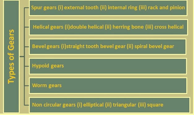
Fig 1 types of Gears as per the axes of transmission
Spur gears
Spur gears have straight teeth cut parallel to the rotational axis. These gears transmit rotation between parallel shafts. The tooth form is based on the involute curve. Practice has shown that this design accommodates mostly rolling, rather than sliding, contact of the tooth surfaces. The involute curve is generated during gear machining processes using gear cutters with straight sides. Near the root of the tooth, however, the tool traces a trochoidal path, providing a heavier, and stronger, root section. Because of this geometry, contact between the teeth occurs mostly as rolling rather than sliding. Since less heat is produced by this rolling action, mechanical efficiency of spur gears is high, often up to 99%. Some sliding does occur, however. And because contact is simultaneous across the entire width of the meshing teeth, a continuous series of shocks is produced by the gear. These rapid shocks result in some objectionable operating noise and vibration. Moreover, tooth wear results from shock loads at high speeds. Noise and wear can be minimized with proper lubrication, which reduces tooth surface contact and engagement shock loads.
Spur gears are the least expensive to manufacture and the most commonly used, especially for drives with parallel shafts. The three main classes of spur gears are (i) external tooth, (ii) internal tooth, and (iii) rack-and-pinion.
- External tooth gears – The most common type of spur gear, has teeth cut on the outside perimeter of mating cylindrical wheels, with the larger wheel called the gear and the smaller wheel the pinion. The simplest arrangement of spur gears is a single pair of gears called a single reduction stage, where output rotation is in a direction opposite that of the input which means that one is clockwise while the other is anti-clockwise. Higher net reduction is produced with multiple stages in which the driven gear is rigidly connected to a third gear. This third gear then drives a mating fourth gear that serves as output for the second stage. In this manner, several output speeds on different shafts can be produced from a single input rotation.
- Internal (ring) gears – Internal gears produce an output rotation that is in the same direction as the input, As the name implies, teeth are cut on the inside surface of a cylindrical ring, inside of which are mounted either a single external tooth spur gear or a set of external tooth spur gears, typically consisting of three or four larger spur gears (planets) usually surrounding a smaller central pinion (sun). Normally, the ring gear is stationary, causing the planets to orbit the sun in the same rotational direction as that of the sun. For this reason, this class of gear is often referred to as a planetary system. The orbiting motion of the planets is transmitted to the output shaft by a planet carrier. In an alternative planetary arrangement, the planets may be restrained from orbiting the sun and the ring left free to move. This causes the ring gear to rotate in a direction opposite that of the sun. By allowing both the planet carrier and the ring gear to rotate, a differential gear drive is produced, the output speed of one shaft being dependent on the other.
- Rack and pinion gears – A straight bar with teeth cut straight across it, is called a rack. Basically, this rack is considered to be a spur gear unrolled and laid out fiat. Thus, the rack-and pinion is a special case of spur gearing. The rack-and-pinion is useful in converting rotary motion to linear and vice versa. Rotation of the pinion produces linear travel of the rack. Conversely, movement of the rack causes the pinion to rotate. The rack-and-pinion is used extensively in machine tools, lift trucks, power shovels, and other heavy machinery where rotary motion of the pinion drives the straight-line action of a reciprocating part. Normally, the rack is operated without a sealed enclosure in these applications, but some type of cover is usually provided to keep dirt and other contaminants from accumulating on the working surfaces.
Helical gears
Helical gears differ from spur gears in that helical teeth are cut across the gear face at an angle rather than straight. Thus, the contact line of the meshing teeth progresses across the face from the tip at one end to the root of the other, reducing the noise and vibration characteristic of spur gears. Also, several teeth are in contact at any one time, producing a more gradual loading of the teeth that reduces wear substantially. The increased amount of sliding action between helical gear teeth, however, places greater demands on the lubricant to prevent metal-to-metal contact and resulting premature gear failure. Also, since the teeth mesh at an angle, a side thrust load is produced along each gear shaft. Thus, thrust bearings must be used to absorb this load so that the gears are held in proper alignment.
The three other principle classes of helical gears are (i) double-helical, (ii) herringbone, and (iii) cross-helical.
- Double helical gears – Thrust loading is eliminated by using two pairs of gears with tooth angles opposed to each other. In this way, the side thrust from one gear cancels the thrust from the other gear. These opposed gears are usually manufactured with a space between the opposing sets of teeth.
- Herringbone gears – Teeth in these gears resemble the geometry of a herring spine, with ribs extending from opposite sides in rows of parallel, slanting lines. Herringbone gears have opposed teeth to eliminate side thrust loads the same as double helicals, but the opposed teeth are joined in the middle of the gear circumference. This arrangement makes herringbone gears more compact than double helicals. However, the gear centers must be precisely aligned to avoid interference between the mating helixes.
- Cross helical gears – This type of gear is recommended only for a narrow range of applications where loads are relatively light. Because contact between teeth is a point instead of a line, the resulting high sliding loads between the teeth requires extensive lubrication. Thus, very little power can be transmitted with cross helical gears.
Bevel gears
Bevel gears have teeth cut on an angular or conical surface unlike spur and helical gears with teeth cut from a cylindrical blank. Bevel gears are used when input and output shaft centerlines intersect.
Teeth are usually cut at an angle so that the shaft axes intersect at 90 deg, but any other angle may be used. A special class of bevels called ‘miter gears’ has gears of the same size with their shafts at right angles. Often there is no room to support bevel gears at both ends because the shafts intersect. Thus, one or both gears overhang their supporting shafts. This overhung load may deflect the shaft, misaligning gears, which causes poor tooth contact and accelerates wear. Shaft deflection may be overcome with straddle mounting in which a bearing is placed on each side of the gear where space permits. There are two basic classes of bevel gears (i) straight tooth and (ii) spirals.
- Straight tooth bevel gears – These gears, also known as plain bevels, have teeth cut straight across the face of the gear. They are subject to much of the same operating conditions as spur gears in that straight tooth bevels are efficient but somewhat noisy. They produce thrust loads in a direction that tends to separate the gears.
- Spiral bevel gears – In spiral bevels, curved teeth provide an action somewhat like that of a helical gear. This produces smoother, quieter operation than straight-tooth bevels. Thrust loading depends on the direction of rotation and whether the spiral angle at which the teeth are cut is positive or negative.
Hypoid gears
Hypoid gears resemble spiral bevels, but the shaft axes of the pinion and driven gear do not intersect. This configuration allows both shafts to be supported at both ends. In hypoid gears, the meshing point of the pinion with the driven gear is about midway between the central position of a pinion in a spiral-bevel and the extreme top or bottom position of a worm. This geometry allows the driving and driven shafts to continue past each other so that end-support bearings can be mounted. These bearings provide greater rigidity than the support provided by the cantilever mounting used in some bevel gearing. Also adding to the high strength and rigidity of the hypoid gear is the fact that the hypoid pinion has a larger diameter and longer base than a bevel or spiral-bevel gear pinion of equal ratio. Although hypoid gears are stronger and more rigid than most other types, they are one of the most difficult to lubricate because of high tooth-contact pressures. Moreover, the high levels of sliding between tooth surfaces, reduces efficiency. In fact, the hypoid combines the sliding action of the worm gear with the rolling movement and high tooth pressure associated with the spiral bevel. In addition, both the driven and driving gears are made of steel, which further increases the demands on the lubricant. As a result, special extreme pressure lubricants with both oiliness and anti-weld properties are required to withstand the high contact pressures and rubbing speeds in hypoids. Despite these demands for special lubrication, hypoid gears are used extensively in rear axles of automobiles with rear-wheel drives. Moreover, they are being used increasingly in industrial machinery.
Worm gears
Worm gear sets consist of a screw-like worm (comparable to a pinion) that meshes with a larger gear, usually called a wheel. The worm acts as a screw, several revolutions of which pull the wheel through a single revolution. In this way, a wide range of speed ratios up to 60:1 and higher can be obtained from a single reduction. Most worms are cylindrical in shape with a uniform pitch diameter. However, a double-enveloping worm has a variable pitch diameter that is narrowest in the middle and greatest at the ends.
This configuration allows the worm to engage more teeth on the wheel, thereby increasing load capacity. In worm-gear sets, the worm is most often the driving member. However, a reversible worm-gear has the worm and wheel pitches so proportioned that movement of the wheel rotates the worm.
In most worm gears, the wheel has teeth similar to those of a helical gear, but the tops of the teeth curve inward to envelop the worm. As a result, the worm slides rather than rolls as it drives the wheel. Because of this high level of rubbing between the worm and wheel teeth, the efficiency of worm gearing is lower than other major gear types.
One major advantage of the worm gear is low wear, due mostly to the full-fluid lubricant film that tends to be formed between tooth surfaces by the worm sliding action. A continuous film that separates the tooth surfaces and prevents direct metal-to-metal contact is typically provided by relatively heavy oil, which is often compounded with fatty or fixed oils such as acid less tallow oil. This adds film strength to the lubricant and further reduces friction by increasing the oiliness of the fluid.
Worm-gear friction is further reduced through the use of metals with inherently low coefficients of friction. For example, the wheel is typically made of bronze and the worm of highly finished, hardened steel. These low-friction materials can be used in worm gears because pressures are more uniformly distributed over the tooth surface than most other gear types. Worm-gear shafts are perpendicular, non-intersecting, and may be positioned in a variety of orientations.
Noncircular gears
Though often overlooked, noncircular gears can provide several types of unusual motion or speed characteristics. Cams and linkages can provide these special motion requirements as well, but noncircular gears often represent a simpler, more compact, or more accurate solution. Servo systems may also be able to do the job, but they are usually more expensive and require more expertise to solve motion problems.
Common requirements handled by noncircular gears include converting a constant input speed into a variable output speed, and providing several different constant-speed segments during an operating cycle. Other applications require combined translation and rotation, or stop-and-dwell motion. Several types of noncircular gears, particularly elliptical gears, generate variable output speeds. Other, less commonly used types are triangular and square gears.
- Elliptical gears – A set of like elliptical gears can run at a constant center distance, but deliver an output speed that changes as they rotate. Elliptical gears come in two basic types (i) unilobe, which rotates about one of two fixed points on its long axis, and bilobe, which rotates about its center. The speed-reduction ratio of these gears varies from 1/K to K during each cycle of rotation, where practical values of K range up to 3. As the gears rotate, the radii of the driving and driven gears change, so that speed first decreases for 1/4 revolution, then increases for 1/4 revolution, etc. These periods of increasing or decreasing speed occur four times per revolution. Elliptical gears are commonly used in packaging and conveyor applications.
- Triangular – A pair of triangular gears has three lobes or high points on the perimeter, rather than the two lobes in elliptical bilobe gears. So triangular gears deliver per revolution six periods of speed increase or decrease rather than four.
- Square. – Gears that are square have four lobes, so they produce eight periods of speed increase or decrease per revolution. Both triangular and square gears have a smaller range of speed ratios than elliptical gears.
Constant speed segments – Where an application requires several constant-speed periods within a cycle, multispeed gears, may be the answer. These gears make the transition between speeds by using special function segments on the gear perimeter between the constant speed sections.
Translation and rotation – For applications requiring both translational and rotational motion, certain gears serve as cam substitutes. Often used in labeling machines, the cam gear duplicates the shape of a part to be labeled and a cam-following rack carries the labeling device at a constant surface speed.
Stop and dwell motion – Some machines must provide either stop and- dwell motion or reverse motion. This is achieved by combining noncircular gears with round gears and a differential (epicyclic gear train).Stop-and-dwell motion is common in indexing mechanisms. Reverse motion is required where a transfer device must operate between two locations.
Gears are generally specified by their (i) type (e.g. spur, bevel, spiral etc.), (ii) material, (iii) size or dimensions, (iv) geometry, and (v) special features, if any.
Gears widely used in numerous machines and systems are of several types, sizes and materials. They require positive and stepped drive. The major applications include the following.
- Speed gear box, feed gear box and some other kinematic units of machine tools
- Speed drives in the machineries of in many industries
- Gear boxes of automobiles
- Speed and / or feed drives of rolling mills and several metal forming machines
- Large and heavy duty gear boxes used in heavy industries such as steel industry
- Gear boxes used in cranes, conveyors and other material handling equipments.
- Precision equipments, clocks and watches
- Industrial robots and toys.

Leave a Comment