Couplings and Their Types
Couplings and Their Types
In all areas of a steel plant, there is a necessity for the reliability and high performance of machinery and equipment. Couplings, serving as vital transmission parts, are no exception to meet higher and more stringent quality requirements needed for the steel plant’s equipment and machinery.
In the simplest of terms, a coupling’s purpose is to transfer rotational movement from one shaft to another. Couplings are used to connect two shafts for torque transmission in varied applications. It may be to connect two units such as a motor and a generator or it may be to form a long line shaft by connecting shafts of standard lengths say 6 m to 8 m by couplings. In addition, couplings are capable of transmitting axial thrust loads between machines and any axial growth that may occur due to high temperature.
Couplings may be rigid or they may provide flexibility and compensate for misalignment. They may also reduce shock loading and vibration. A wide variety of commercial shaft couplings are available ranging from a simple keyed coupling to one which requires a complex design procedure using gears or fluid drives etc. However there are two main types of couplings (Fig 1) which are (i) rigid couplings, and (ii) flexible couplings.
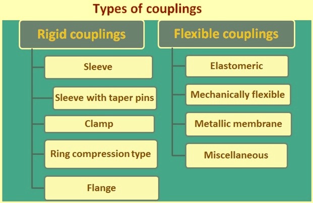
Fig 1 Types of couplings
Rigid couplings
Rigid couplings are used for shafts having no misalignment. Since these couplings cannot absorb any misalignment the shafts to be connected by a rigid coupling must have good lateral and angular alignment.
As compared with flexible couplings, rigid couplings have limited application. Rigid couplings do not have the ability to compensate for shaft misalignments and are therefore used where shafts are already positioned in precise lateral and angular alignment. Any misalignment between shafts will create high stresses and support bearing loads.
Rigid couplings are typically used in applications involving vertical drivers. The rigid coupling transmits not only the rotational motion from the driver (typically an electric motor) to the rotating element of the equipment, but any axial movement (up or down) that occurs between the two pieces of equipment is also transmitted between them. Because of rigidity of the couple, the equipment must be in precise alignment and cannot accept any misalignment.
Since the rigid coupling directly connects the equipment shaft to the motor shaft, the equipment transfers any axial thrust to the motor. The weight of the shafting and rotating element must be taken up by special thrust bearing in the motor or motor support. If a motor stand with a thrust bearing is not used, the motor must be selected and designed to carry the weight of the rotating element, as well as the axial thrust.
The most common design of the rigid coupling is of a split configuration. The coupling is split along axial centerline.
The rigid coupling is also available in a flanged configuration. This configuration utilizes two couplings flanges bolted together, and may include a spacer to allow for the removal of a mechanical seal.
Proper design and installation of the bolted flanges allows for the transmission of the driver torque to occur with the friction contact of the flanges. In this case, the flange bolts are not subject to a shearing stress from the torque.
In the case of split rigid couplings, the adjustment is usually done using shim or special tools that lift the rotating element. Once the element is located in the proper location, the bolts on the split rigid coupling are tightened to the recommend torque values. For flanged rigid couplings, adjusting plates are utilized to set the proper vertical position.
Rigid couplings are constructed of all metal materials. This allows the coupling to be used in applications that have high temperatures, high speeds, a solvent atmosphere, or high driver horsepower. Rigid couplings by virtue of their simple rugged design are generally able to transmit more power than flexible couplings of comparable size, but this is not an important advantage except in high horsepower applications.
Rigid couplings are of following types.
- Sleeve coupling – One of the simple types of rigid coupling is a sleeve coupling which consists of a cylindrical sleeve keyed to the shafts to be connected. The sleeve transmits the torque from one shaft to the other. Normally sunk keys are used and in order to transmit the torque safely it is important to design the sleeve and the key properly. The key design is usually based on shear and bearing stresses.
- Sleeve coupling with taper pins – Torque transmission from one shaft to another may also be done using pins.
- Clamp coupling – A typical clamp coupling essentially consists of two half cylinders which are placed over the ends of the shafts to be coupled and are held together by through bolt.
- Ring compression type couplings – The coupling consists of two cones which are placed on the shafts to be coupled and a sleeve that fits over the cones. Three bolts are used to draw the cones towards each other and thus wedge them firmly between the shafts and the outer sleeve.
- Flange coupling – It is a very widely used rigid coupling and consists of two flanges keyed to the shafts and bolted. The main features of the design are essentially (I) design of bolts, (ii) design of hub, and (iii) overall design and dimensions.
Flexible couplings
Flexible couplings are more commonly used to transmit driving torque between a prime mover and a rotating element of the equipment. Although designed to accommodate misalignment, normally it is recommended not to use a flexible coupling to compensate for misalignment of the rotating element of the equipment and driver shafts. The purpose of the flexible coupling is to compensate for temperature changes in the couplings and shafts, and to permit axial movement of the shafts without interference with each other while power is transmitted from the driver to the rotating element of the equipment.
There are two disciplines for the application of flexible couplings. They are (i) the miniature discipline, which covers couplings used for office machines, servomechanisms, instrumentation, and light machinery etc., and (ii) the industrial discipline, which covers couplings used in the steel industry, the petrochemical industry, utilities, off-road vehicles, and heavy machinery etc. The four basic categories of flexible industrial couplings and their general operating principles are as follows.
- Elastomeric couplings – In general, these couplings obtain their flexibility from stretching or compressing a resilient material (rubber, plastic, etc.). Some sliding or rolling may take place, but it is usually minimal.
- Mechanically flexible couplings – In general, these couplings obtain their flexibility from loose-fitting parts and/or rolling or sliding of mating parts. Therefore, they usually require lubrication unless one moving part is made of a material that supplies its own lubrication needs (e.g., a nylon gear coupling). Also included in this category are couplings that use a combination of loose-fitting parts and/or rolling or sliding, with some flexure of material.
- Metallic membrane couplings – In general, the flexibility of these couplings is obtained from the flexing of thin metallic disks or diaphragms.
- Miscellaneous couplings – These couplings obtain their flexibility from a combination of the mechanisms described above or through a unique mechanism like spring couplings.
The elastomeric flexible coupling typically utilizes a plastic or rubber element that allows for the temperature growth or axial movement. The elastomeric element is sufficiently resistant to fatigue failure to provide an acceptable life compared to the cost of the coupling.
Most elastomeric flexible couplings do not use lubrication, and are loaded in shear. Although not as common, jaw-and-pin and bushing design couplings are designed to be loaded in compression.
Due to the limitations of the flexible element, this type of coupling is used up to 37 kW and 3600 rpm. In applications greater than that, the coupling becomes bulky and more expensive than a non-elastomeric flexible.
The coupling insert can be provided as a split sleeve or a solid sleeve. The split sleeve allows for the replacement of the sleeve on non-spacer couplings without moving the equipment. A solid sleeve design is stronger than the split sleeve and can handle higher torque requirements. Because it is a solid element, the design eliminates the sleeve-retaining ring, which could be a safety hazard. The solid sleeve is also typically used with spacer couplings.
There are a number of different types of mechanical, flexible couplings. The mechanical nature of this type of coupling allows for nearly unlimited horsepower and torque capabilities.
A common type of mechanical flexible coupling is the gear coupling. This coupling consists of two shaft hubs with external gear teeth cut integrally on the hubs, sleeve members having internal gear teeth, and a floating spacer. Because of the close fitting tolerances and the sliding motion of the gear, lubrication, such as clean grease or oil, is required to prevent wear of the rubbing surfaces. The gear coupling provides good torque characteristics.
A roller-chain flexible coupling utilizes two sprocket-like members, or hubs, that are mounted on the driver and the equipment shafts. They are connected by a section of roller chain. This type of coupling is typically applied in low speed services.
A hybrid design that utilizes features of both the elastomeric and mechanical flexible coupling is the spring grid style. This design utilizes two shaft hubs, an elastomeric grid, which couples the two hubs, and a split cover, which holds the grid in place.
Other types of flexible couplings include limited end float, metal disk, diaphragm, and jaw- type. Each of these couplings has special uses due to the application or the size/type of the equipment.
The three functions of flexible couplings are given below.
- They must transmit power. The maximum rotational speed at which they operate is important when selecting a flexible coupling. Subsequent motion of bearings and/or foundations may cause misalignment. The latter should remain within the limits prescribed by manufacturers for the selected coupling.
- Flexible couplings must couple two pieces of rotating equipment, equipment with shafts, flanges, or both. These interface connections are numerous.
- Flexible couplings must also transmit power efficiently. Usually, the power lost by a flexible coupling is small, although some couplings are more efficient than others. Power is lost in friction heat from the sliding and rolling of flexing parts and at high speed, windage and frictional losses indirectly cause loss of efficiency. The efficiency of the flexible couplings is generally more than 99 %.
Couplings transmit torque and motion between shafts in the presence of various types of misalignment namely (i) angular, (ii) parallel, (iii) torsional, and (iv) axial. Flexible couplings must accommodate the following three types of misalignment.
- Parallel offset – Axes of connected shafts are parallel but not in the same straight line. It is also called radial misalignment.
- Angular – Axes of shafts intersect at the center point of the coupling, but not in the same straight line.
- Combined angular and offset – Axes of shafts do not intersect at the center point of the coupling and are not parallel.
Most flexible couplings are designed to accommodate axial movement of equipment or shaft ends. In some cases (e.g., motors) couplings are required to limit axial float of the equipment shaft to prevent internal rubbing of a rotating part within its case.
Accommodation of misalignment and end movement must be done without inducing abnormal loads in the connecting equipment. Generally, machines are set up at installation quite accurately. There are many things that force equipment to run out of alignment. The thermal effects of handling hot and cold fluids cause some movement in the vertical and axial direction, together with differentials of temperature in driver media such as gas and steam. The vertical motions can be a result of support structure expansions due to temperature differences, distortion due to solar heating, axial growth or a combination of these. Horizontal motions are usually caused by piping forces or other structural movements, temperature differentials caused by poor installation practices, and expansions or contractions caused by changes in temperature or pressure differentials of the media in the system.
It is a fact of life that machinery appears to live and breathe, move, grow, and change form and position; this is the reason for using flexible couplings. A flexible coupling is not the solution to all movement problems that can or could exist in a sloppy system. Using a flexible coupling in the hope that it will compensate for any and all motion is naive. Flexible couplings have their limitations. The equipment or system designer must make calculations that will give a reasonable estimate of the outer boundaries of the anticipated gyrations. Unless those boundaries are defined, the equipment and system designer may just be transferring equipment failure into coupling failure.
One thing to remember is that when subjected to misalignment and torque, all couplings react on connected equipment components. Some produce greater reactionary forces than others and if overlooked, can cause shaft failures, bearing failures, and other failures of equipment components. They may also excite vibrations with time-varying reactions.
Static reactions of flexible couplings may overload or unload nearby bearings whose selection is often based on the weight of the rotor they support. It may happen that the static reaction of a flexible coupling is near the value of the rotor weight.
Dynamic reactions from flexible couplings cause vibrations. The most common cause for vibrations originates from rotor unbalances. Balancing norms specify the amount of residual unbalance that is admissible on rotors. These depend on specific balancing grades for different types of applications, the rotor weight and maximum rotational speed.
To a given admissible residual unbalance corresponds a centrifugal force. The dynamic reactions of the couplings become a nuisance when they exceed the contribution of these centrifugal forces. This is shown to be the case with gear couplings, much less with other types of couplings like disc and elastomeric one.
Rigid couplings produce the greatest reactions. Elastomeric couplings produce moderate to low moments and forces that are slightly dependent on torque. Mechanically flexible couplings such as gear, chain, and grid couplings produce high to moderate moments and forces on equipment that are a function of torque and misalignment. Metallic membrane couplings produce relatively low moments and forces which are relatively independent of torque.
The most commonly used flexible couplings today are those that produce the greatest flexibility (misalignment and axial capacity) while producing the lowest external loads on equipment.
Flexible couplings are a vital part of a mechanical power transmission system. Unfortunately, many system designers treat flexible couplings as if they were a piece of hardware. The amount of time spent in selecting a coupling and determining how it interacts with a system should be a function not only of the cost of the equipment but also how much downtime it will take to replace the coupling or repair a failure. In some cases the process may take only a little time and be based on past experience; however, on sophisticated systems this may take complex calculations, computer modeling, and possibly even testing. A system designer or coupling user just cannot put any flexible coupling into a system with the hope that it will work. It is the system designer or the user’s responsibility to select a coupling that will be compatible with the system.
Flexible coupling manufacturers are not usually system designers; rather, they size, design, and manufacture couplings to fulfill the requirements supplied to them. Some coupling manufacturers can offer some assistance based on past exposure and experience. They are the experts in the design of flexible couplings, and they use their know-how in design, materials, and manufacturing to supply a standard coupling or a custom-built one if requirements so dictate. A flexible coupling is usually the least expensive major component of a rotating system. It usually costs less than 1 %, and probably never exceeds 10 %, of the total system cost. And yet it can cause severe financial losses when not well selected and operated
Flexible couplings are called upon to accommodate for the calculated loads and forces imposed on them by the equipment and their support structures. Some of these are motions due to thermal growth deflection of structures due to temperature, torque-load variations, and many other conditions. In operation, flexible couplings are sometimes called on to accommodate for the unexpected. Sometimes these may be the forgotten conditions or the conditions unleashed when the coupling interacts with the system, and this may precipitate coupling or system problems. It is the coupling selector’s responsibility to review the interaction of the coupling with that system. When the coupling’s interaction with the system is forgotten in the selection process, coupling life could be shortened during operation or a costly failure of coupling
One thing to remember is that when subjected to misalignment and torque, all couplings react on the connected equipment components. Some produce greater reactionary forces than others and if overlooked, can cause shaft failures, bearing failures, and other failures of equipment components. They may also excite vibrations with time-varying reactions. This last point usually receives less attention.
Successful coupling selection requires a clear understanding of application conditions. The major factors governing coupling selection are given below.
- Torque and power rating
- Shaft misalignment
- Lateral and axial flexibility of couplings
- Torsional flexibility
- Backlash
- Rotational velocity error
- Service conditions
There are a set of minimum requirements for couplings needed in the steel industry. These robust specifications require couplings to have some of the following features.
- Flexible
- Steel material
- Corrosion resistant
- Large spacer (125 mm shaft separation)
- Keyed to shaft as standard and for shafts greater than 62.5 mm shall be provided with a tapered fit
- Rated for maximum driver horsepower
- Coupling components shall be balanced
There is a more stringent specification for couplings in steel plant for equipments that operate continuously for extended periods, that cannot be stopped, and that are critical to operation.
In any case, and especially for critical applications, the coupling should be selected based on reliability, maintainability, and possibility for regular observation.
The reliability of the design of the coupling, while in or out of operation, is to be unaffected by various forces, including speed, deflection, stretch, compression, shock loading and others. Reliability is also determined by the age and environment of the coupling components. Coupling elastomers should not be affected by time or temperature.
Maintainability is determined by the ease of installation, accessibility in the machine, availability of replaceable components and the number of parts in the coupling.
The possibility for regular observation is the ability to determine the condition of the coupling, such as wear showing up in lube oil of gear coupling, or as vibration that is detected.

Leave a Comment