Understanding the Process of Continuous Casting of Steel
Understanding the Process of Continuous Casting of Steel
Continuous casting (CC) of steel is a process whereby liquid steel is solidified into a semi-finished steel product (billet, bloom, beam- blank, round or slab) for subsequent rolling in the rolling mills. The basic operation of a CC machine is to convert liquid steel of a given composition into a strand of desired shape and size through a group of operations like mould operation, spray cooling zone, straightener operation, etc. For successful continuous casting, it is necessary to understand the process behaviour under different conditions for these operations. The process of continuous casting basically comprised of the following sections.
- A tundish, located above the mould, to receive the liquid steel from steel teeming ladle and to feed it to the mould at a regulated rate.
- A primary cooling zone consisting of water cooled copper mould through which the liquid steel is fed from the tundish for generating a solidified outer steel shell sufficiently strong enough to maintain the strand shape as it passes into the secondary cooling zone.
- A secondary cooling zone in association with a containment section positioned below the mould, through which the steel strand (still mostly liquid) passes and is sprayed with water or a mix of water and air (air mist) for further solidifying of the steel strand.
- A section for the unbending and straightening of steel strand. This section is not there in the straight vertical casting machines.
- A cutting section consisting of cutting torches or mechanical shears for the cutting of the solidified steel strands into desired lengths for removal.
- A run out table to cooling beds or directly to a product transfer area.
In the CC process, liquid steel flows from the steel teeming ladle, through a tundish into the mould. It is usually protected from exposure to air by a slag cover over each vessel (ladle, tundish, and mould) and by ceramic tubes between the vessels.
To start the process of the continuous casting, a dummy bar (which is connected to an external mechanical withdrawal system) is inserted into the mould and positioned so that the top of the dummy bar closes the bottom of the mould. Liquid steel is delivered in a steel teeming ladle to the casting floor where it is poured at a controlled rate into the tundish. Liquid steel flows through nozzles in the bottom of the tundish and fills the mould. When the liquid steel level in the mould reaches a predetermined position, withdrawal of the dummy bar is initiated. Once in the mould, the liquid steel solidifies against the water cooled copper mould walls to form a solid shell. Drive rolls lower in the CC machine continuously withdraw the dummy bar from the mould. The withdrawal speed of the dummy bar is preset based on the casting speed required or the liquid steel flow rate from the tundish. When the dummy bar head, which is now attached to the solidified shape being cast, reaches a certain position in the withdrawal system, it is mechanically disconnected and the dummy bar is removed. The solidified cast shape continues through the withdrawal system to the cutting equipment at a rate (casting speed) that matches the flow of incoming liquid steel, so the process ideally runs in steady state.
Solidification of the liquid steel, which has started in the water cooled mould, continues progressively as the steel strand moves through the CC machine. Solidification begins at the liquid steel meniscus level in the mould forming a steel shell in contact with the walls of the mould. The distance from the meniscus level to the point of complete solidification within the CC machine is called the metallurgical length. The point of complete solidification is to occur naturally ahead of the cutting point of the strand and in many CC machines it is ahead of the straightener.
Casting conditions are established such that the strength of the solidified steel shell leaving the mould is sufficient to withstand the ferrostatic pressure of the liquid steel in the mould. To prevent sticking of the solidified shell to the mould wall, the mould is oscillated in a vertical direction. Friction between the steel shell and the mould is minimized by the introduction of mould lubricants such as oils or fluxes which form a fluid slag.
Below mould exit, the solidifying steel shell acts as a container to support the remaining liquid steel. Additional heat is removed from the strand in the secondary cooling zones which consist of a series of water and air mist sprays. Flow rates are closely controlled to obtain optimum cooling rates and to maintain the surface temperature until the liquid core is solid. Support roll units are provided to contain the strand to avoid transverse movement and to prevent bulging of the hot solidifying shell from internal ferrostatic pressure. The strand cooling and containment system are designed, as is the mould, to prevent external and internal defects in the cast section and to ensure the required steel product quality.
The secondary cooling and containment area is followed, on certain types of machine, by a bending unit and a straightener which is present in all machines.
After straightening, the cast section is cut to the desired length either by torches or shears. The hot cut lengths are then either conveyed by a run out roller table to cooling beds or grouped and transferred directly to subsequent rolling operations.
Requirements from liquid steel
Temperature control is critical for the CC process. Generally the liquid steel for the continuous casting is to be tapped at higher tapping temperature. The tapping temperature is higher since it has to compensate for the heat losses associated with the increased transfer time to the CC machine. The temperature for the continuous casting is also required to be maintained within closer limits. If the temperature is too high, there is usually a breakout; and if the temperature is too low, premature solidifying of liquid steel in the tundish nozzles usually occurs. Casting temperature can also affect the crystallization structure of the cast steel. Optimum structures are normally obtained with low superheats that need to be uniform throughout the entire casting process. The common practice generally used to reach the uniform temperature is to stir the liquid steel in the teeming ladle by the injection of a small quantity of argon into the liquid steel.
Liquid steel for the continuous casting is also required to be fully deoxidized (killed) to prevent the formation of blowholes or pinholes at or close to the surface of the cast steel. These blowholes or pinholes usually result into seams in subsequent rolling process. Normally two practices are used for deoxidation of liquid steel depending on the grade of the steel being produced and the steel product applications. These are (i) silicon deoxidation with a small addition of aluminum for coarse grain steels, and (ii) aluminum deoxidation for fine grained steel. Silicon killed steels are easier to cast than aluminum killed steels. This is because deposits of alumina in the tundish nozzle, which cause nozzle blockage, are avoided.
Tundish application
In the CC process, the liquid steel is transferred at first from a ladle into the tundish. Then the liquid steel is distributed into different strand of moulds, through a nozzle for each strand. The tundish is essentially a rectangular box with nozzles located along the bottom. The following is made possible because of tundish.
- To reach stability of the liquid steel streams entering the casting mould, and in turn, to achieve a constant casting speed.
- To cast a sequence of heats.
- To change over the empty steel teeming ladle for a full steel teeming ladle without interrupting the flow of liquid steel in the moulds.
- To make a mixed grade with steel from two different grades of two different heats, if needed.
- To provide possibility to prevent inclusions and slag from entering tundish and thus slipping into mould
Tundishes are normally preheated before the casting to minimize heat losses from the liquid steel during the initial stages of casting and thus avoid metal solidification, particularly in the critical nozzle areas. Tundish covers are also used to reduce radiant heat losses throughout the casting operation.
Liquid steel shrouding
During the open stream casting, the liquid steel flows directly, through the air, from the steel teeming ladle to the tundish or from the tundish to the mould. Under these conditions, the unprotected liquid steel stream picks up oxygen (and some nitrogen) from the air and harmful inclusions are formed in the liquid steel. These inclusions are transferred into the casting mould where they are either retained within the cast section or float to the surface of the liquid steel. Those present on the liquid steel surface are later trapped in the solidifying shell and either result in surface defects or a break out the shell below the mould. In addition to the direct formation of inclusions in the exposed steel stream, air entrained in the stream can also react with liquid steel both in the mould and tundish.
To avoid these issues normally CC operation is carried out employing shrouded stream of liquid steel. Emphasis is usually placed on shrouding the liquid steel stream between the tundish and mould because of severity of the problem. However, ladle to tundish stream shrouding is now used widely, especially in case of the casting of aluminum killed steels where the prevention of alumina inclusions is of utmost importance. There are two basic types of shrouding with a large number of variations and combinations. These are namely (i) gas shrouding, and (ii) ceramic tube shrouding.
In case of gas shrouding, nitrogen or argon is used as the protection gas. Ceramic tube shrouds are normally used for casting of aluminum killed steel. They are used both between the steel teeming ladle and tundish, and between the tundish and the mould. One end of the tube is attached to the ladle (or tundish) with the other end immersed in the steel when the tundish or mould is being filled with the liquid steel. Ceramic tubes are generally made of fused silica or alumina graphite.
The mechanical design of the ceramic tube is important, especially at the exit end that is immersed in the liquid steel. One type is a straight through design. Another type, generally used in the mould, is having a multiport (opening) design, such as a bifurcated tube with the bottom of the tube closed and two side openings located near the bottom of the tube. This type of shroud avoids deep penetration of the pouring stream into the mould and modifies the flow pattern in the mould. Thus, the inclusions in the pouring stream are not entrapped in the solidifying section but rise to the surface of the liquid steel and are removed with the slag formed by the casting powder.
Liquid steel flow control
Some of the important phenomena which govern the continuous casting process and determine the quality of the cast steel are described here. Liquid steel flows into the mould through the ports in the submerged entry nozzle (SEN), which is usually bifurcated. The high velocities produce Reynolds numbers exceeding 100,000 and fully turbulent behaviour. Argon gas is also usually injected into the nozzle to prevent clogging. The resulting bubbles provide buoyancy that significantly affects the flow pattern in the nozzle as well as in the mould. These bubbles also collect inclusions and may become entrapped in the solidifying steel shell, leading to serious surface defects in the cast steel product. The liquid steel jet leaving the nozzle flows across the mould and impinges against the steel shell solidifying at the narrow face. The jet carries superheat, which can erode the steel shell where it impinges on locally thin regions. In the extreme case, this erosion can cause a breakout, where the liquid steel bursts through the steel shell.
Generally the liquid steel jet impinging on the narrow face splits to flow upwards towards the top free surface and downwards toward the interior of the strand. Flow recirculation zones are formed above and below each jet. This flow pattern changes radically with increasing argon injection rate or with the application of electromagnetic forces, which can either brake or stir the liquid. The flow pattern can fluctuate with time, leading to defects, so transient behaviour is important.
Liquid flow along the top free surface of the mould is very important for the quality of the cast steel. The horizontal velocity along the interface induces flow and controls heat transfer in the liquid and solid flux layers, which float on the top free surface. Inadequate liquid flux coverage leads to non-uniform initial solidification and a variety of surface defects.
If the horizontal surface velocity is too large, the shear flow and possible accompanying vortices can entrain liquid flux into the steel. This phenomenon depends greatly on the composition dependent surface tension of the interface and possible presence of gas bubbles, which collect at the interface and may even create foam. The flux globules then circulate with the steel flow and may later be entrapped into the solidifying steel shell lower in the CC machine to form internal solid inclusions.
The liquid steel contains solid inclusions, such as alumina. These particles have various shapes and sizes and move through the flow field while colliding to form larger clusters and may attach to bubbles. They either circulate up into the mould flux at the top surface, or are entrapped in the solidifying shell to form embrittling internal defects in the final cast steel.
Casting powder is added to the top surface to provide thermal and chemical insulation for the liquid steel. This oxide-based powder sinters and melts into the top liquid layer that floats on the top free interface of the steel. The melting rate of the powder and the ability of the molten flux to flow and to absorb detrimental alumina inclusions from the steel depend on its composition. It is governed by time-dependent thermodynamics. Some liquid flux resolidifies against the cold mould wall, creating a solid flux rim which inhibits heat transfer at the meniscus. Other flux is consumed into the gap between the steel shell and mould by the downward motion of the steel shell, where it encourages uniform heat transfer and helps to prevent sticking.
Periodic oscillation of the mould is needed to prevent sticking of the solidifying shell to the mould walls, and to encourage uniform infiltration of the mould flux into the gap. This oscillation affects the level fluctuations and associated defects. It also creates periodic depressions in the shell surface (called oscillation marks), which affect heat transfer and act as initiation sites for cracks.
Mould and heat transfer
The primary function of the mould system is to contain and start solidification of the liquid steel to achieve the following objectives.
- Shape of the cast product (overall configuration and shell thickness)
- Temperature distribution
- Internal and surface quality. This includes cast structure, chemical uniformity together with an absence of cracks, porosity and non?metallic inclusions.
One of the most important features of the mould is its heat transfer ability. A mould is basically a box structure which contains an inner lining fabricated from a copper alloy that serves as the interface with the liquid steel being cast. There are small water passages between the inner liner and supporting structure for the mould cooling water that absorbs heat from the solidifying liquid steel in contact with the liner. The lubrication of mould allows better heat transfer at the upper part of the mould. One more factor which influences heat transfer at this mould surface is the mould taper. This tends to increase heat transfer because it opposes the air gap formation between the steel shell and the mould surface.
Besides the heat transfer ability, the high temperature strength and the resistant against the mould wear and mould deformation are also very important. Although the material of construction of the inner lining is usually a high purity cold rolled copper, copper with small amounts of silver is commonly used to obtain increased elevated temperature strength. The working surface of the liner is often plated with chromium or nickel to provide a harder working surface and also to avoid copper pickup on the surface of the cast strand.
Secondary cooling, strand containment and withdrawal
In the recent CC machines, secondary cooling, strand containment and withdrawal form a closely integrated and interlocked system that also includes strand bending and straightening. In the earlier designs of CC machines, there was a greater functional as well as physical separation of the components of this part of the casting operation.
Secondary cooling and the containment and withdrawal system extends from the bottom of the mould through complete solidification of the strand to the cut off operations. The system is capable of producing a cast section which has the proper shape along with the internal and surface quality. For achieving this, the solidifying section leaving the mould is cooled in a series of spray zones and contained and withdrawn by a series of roll assemblies until the solidified cast section reaches the cut off machine and horizontal run out table.
The secondary cooling system is usually divided into a number of zones to control the cooling rate as the cast strand progresses through the CC machine. This system normally consists of water sprays or air water mist sprays that are directed at the strand surface through openings between the containment rolls.
The main heat transfer functions of the secondary cooling system are to provide the following.
- The required amount of water for achieving the complete solidification under the constraints of the CC operation such as steel grade, and casting speed etc.
- The system has the capability for regulating the thermal conditions of the strand from below the mould to the cut off operation such as strand surface temperature and thermal gradients in the strand.
- Auxiliary functions such as cooling of the containment rolls.
It is essential that both the temperature levels and the thermal gradients are controlled in the steel strand for avoiding the occurrence of surface and internal defects such as improper shape and cracks. At high temperature, the strength properties of the steel shell have a critical role to play in its ability to withstand the external and internal forces that are imposed by the CC operation. The primary forces are those exerted by the ferrostatic pressure of the liquid core and the traction of the withdrawal operation. In particular, the ductility of steel close to the solidus temperature is low and the steel shell is prone to crack formation. It is important to control temperature gradients because thermal strains can be caused which exceed the strength of the steel resulting in cracks. Excessive thermal strains result from changes in the heat extraction rate by either over or under cooling. The under cooling conditions can occur by reheating, which is produced when spray cooling is terminated improperly and the strand reheats by heat transfer from the interior with an increase in temperature before decaying by radiation heat transfer to the environment. Under these conditions, excessive strains and cracks can result. The effect can be reduced by extending and varying the water spray cooling operation to provide a smooth transition with the radiation cooling area.
Hence, during the design of the secondary cooling system, the thermal conditions along the strand are to be established which satisfy the integrity and quality of the cast steel. For example, the surface temperatures along the strand are specified. They are normally in the range of 1200 deg C to 700 deg C. Based on this information the cooling rates along the strand are determined from heat transfer equations. Important parameters in these calculations include the convection heat transfer coefficient of the water sprays and the water amount of water per unit area of surface contact (water flux). The type and number of spray nozzles, nozzle position with respect to the steel strand surface, and water pressure are selected to provide the required water flux and distribution throughout the secondary cooling zones. Multiple nozzles are normally used at each level along the steel strand which has an overlapping pattern.
Usually a series of cooling zones is established along the strand, each of which has the same nozzle configurations and heat transfer characteristics. The water flux in successive zones decreases, since the required cooling rates decrease along the length of the strand.
During the CC operation, changes in the water flux are made to compensate for changes in casting conditions such as casting speed, strand surface temperature, cooling water temperature and steel grade.
The spray water system is normally a recirculating system.
The steel strand is contained by a series of retaining rolls which extend across its two opposite faces of the cast sections in a horizontal direction. Edge rolls can also be positioned across the other pair of faces in a direction perpendicular to the casting direction to further enhance containment. The mechanical strand containment and withdrawal equipment forms an integral part of the secondary cooling system. The basic functions of this equipment are namely (i) to support and guide the strand from the mould exit to the strand cut off operations, and (ii) to drive the strand at a controlled speed through the CC machine. The final objective in both of these functions is to minimize the mechanical stress and strains incurred during the CC process.
Strand support involves the restraint of the solidifying steel shape that consists of a solid steel shell with a liquid core. The ferrostatic pressure, created by the height of liquid steel present, tends to bulge the steel especially in the upper levels just below the mould where the solidified shell thickness is small. Bulging at this location can cause cast steel defects such as internal cracks, skin rupture and a breakout. Bulging is controlled by an appropriate roll spacing which is normally very close just below the mould. The roll spacing progressively increases in the lower levels of the CC machine as the skin thickness increases. All the four faces of the cast strand are generally supported below the mould and normally two faces are supported at the lower levels. In addition to ferrostatic pressure and skin thickness, roll spacing is also based on strand surface temperature and the grade of steel cast.
In addition to contain the strand, the series of rolls that guide the strand through a prescribed arc from the vertical to the horizontal plane is to be strong enough to withstand the bending reaction forces. During bending, the outer radius of the solid steel shell is in tension while the inner radius is in compression. The resulting strain which is a function of the radius of the arc and the strength of the particular steel grade being cast, can be critical. Excessive strain in the outer radius results in the steel failure and surface cracks. For minimizing the occurrence of surface defects but, at the same time, maintaining a minimum effective arc radius, triple point bending is presently adopted (three arcs, with progressively smaller radii).
A multi roll straightener is usually installed after the completion of bending. This straightener straightens the cast strand and completes the transition from the vertical to horizontal plane. During straightening the strand is unbent which reverses the tension and compression forces in the horizontal faces of the strand.
The strand is drawn through the different parts of the CC machine by drive rolls which are normally located in the vertical, curved and horizontal roll sections. This multiple drive roll system is designed to produce compression forces in the surface of the strand to improve the surface quality. The objective is to push the strand through the CC machine, as opposed to the pulling of the strand with the associated tensile stresses that tend to cause surface defects. In addition, the use of multiple sets of drive rolls distributes the required traction force along the length of the cast strand and as a result reduces the harmful effects of tensile forces. The proper placing of drive rolls can also reduce adverse bending and straightening strains by exerting an offsetting compression force (by placing drive rolls before a set of bending rolls). In all the cases, the pressure exerted by the drive rolls to grip the strand is not to be excessive. Excessive pressure can deform the shape of the section being cast.
After the straightening, the cast strand is conveyed on roller tables to the cut off machine where the section is cut to the desired length. There are two types of cut off machines namely (i) oxy- fuel torches, and (ii) mechanical shears. Oxy-fuel torches are generally used for large sections such as slabs and blooms. Smaller sections such as billets are either cut by torches or by shears. The cast steel product is then either grouped or transported directly to the rolling mills or to the cooling beds which are mainly of the walking beam type to maintain the cast steel straightness.
The schematics of CC process and the phenomena in the mould region are shown in Fig 1.
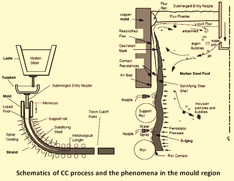
Fig 1 Schematics of CC process and the phenomena in the mould region

Leave a Comment