Steel Teeming Ladle and its Refractory Lining
Steel Teeming Ladle and its Refractory Lining
Steel teeming ladle (STL) is needed in a steel plant to contain and transport liquid steel from the steel making furnace to the casting facility. These days STL is used in a significantly more complex manner than the older steel melting shops where ladles were used simply to transport liquid steel from a steel making furnace to the ingot moulds.
Other functions carried out in the STL are temperature control, deoxidation, additions of carburizer and ferro-alloys and inclusion floatation. In the recent past, the demand for various grades of steel with stringent specifications has increased considerably. These steels are produced using secondary refining processes. The lining of the STL must withstand increasingly severe service conditions associated with the secondary refining processes. These severe conditions are longer holding time, higher liquid temperature and arc/chemical heating. Rinsing with inert gas and degassing of the liquid steel, alloying and use of synthetic slag also accelerate the wear of lining. Because of these activities the demand on the quality of STL refractories has increased very much.
In present day steel melting shops STL functions as traveling components of skimming, rinsing, reheating, and degassing processes. The exposure time for a given heat in these shops has expanded from two to five times of the time earlier needed for ingot teeming.
STL is also required to conserve heat by minimizing heat loss during transport and during the various process steps. In this regard, significant developments have been made to properly preheat ladles prior to the first heat, and to cycle ladles on subsequent heats in a manner to minimize heat losses.
STL is designed to be heat resistant and strong. Also it is necessary to heat insulate the ladle. Proper heat insulation is needed so that the liquid steel contained in the STL remains at a proper temperature.
The refractory lining life of STL must be predictable and reproducible for safety reasons and to avoid process delays. STLs are often removed from circulation for carrying out maintenance of the lining. This can affect adequate supply of ladles for the steel production. Also the cost of refractories for STL is significant and disposal cost of spent linings is also quite substantial.
The selection of the most suitable refractory lining depends on a number of factors which include the circulation cycle of STL, secondary steel making processes, steel quality, ladle availability, new refractory developments, shop logistics and the cost of refractory per ton of crude steel produced.
Ladle circulation cycle
Ladle turnaround time is the time needed to complete one circulation cycle and is important for the smooth running of the steel melting shop. Normally it takes several hours from one steel tapping to next steel tapping in a ladle. Ladle turnaround time decides the number of ladles that are required to be put into circulation. The ladle circulation cycle involves the following steps.
• Inspection and maintenance of STL ? STL is required to hold liquid steel at temperatures of around 1600 deg C to 1650 deg C for long durations. These high temperatures along with the different processes which are required to be carried out in the STL mean that there is wear of the lining. Hence STL needs continuous inspection and maintenance to keep it in good shape. Processing of STLs between heats is necessary to remove ladle slag and provide for ladle well cleanout, slide gate inspection and repairs, and ladle well sanding.
• Ladle preheating – After the inspection and maintenance STL is preheated for bringing the ladle inside temperature to a desirable value. If the ladle inside temperature is already at desired level after inspection and maintenance then this step can be bypassed.
• Liquid steel tapping – The liquid steel from the primary steelmaking process is tapped into the STL. While tapping the liquid steel, precaution is needed that sufficient free board is available in STL for carrying out the secondary refining processes.
• Ladle transportation ?STL with liquid steel is transported usually on a transfer car to secondary refining processes. During this step, waiting of the ladle with liquid steel is to be avoided for the control of temperature loss.
• Secondary refining processes – Liquid steel in the STL undergoes various treatments in the secondary refining processes as per the requirements of the steel grade. At this stage adjustment of chemical composition and temperature of liquid steel is carried out. Rinsing of liquid steel is also carried out for reducing stratification and making the steel more homogeneous.
• Continuous casting – After the secondary steel making processes ladle covering compound is put on the liquid surface in the STL to reduce the heat loss at the top due to radiation and the STL is taken to the ladle turret of the continuous casting (CC) machine for the casting of the liquid steel. A ladle cover is also used for reducing the heat losses. After the CC operation is over, the left over liquid steel and slag is dumped in the dumping ladle and the STL is sent to ladle inspection and maintenance area.
The ladle cycle is shown in Fig 1.
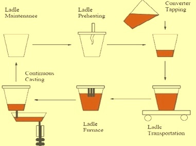
Fig 1 Ladle cycle
Preheating of STL and cover devices have improved significantly in recent years, and many types of pre-heaters (ladle horizontal or vertical) are available. There are several benefits of proper ladle preheating and cycling which include longer refractory life by minimizing thermal shock. The actual ability to rapidly cycle STLs and make the most efficient use of preheaters can vary significantly between operations, depending on shop layout and ladle transfer ability.
Steel making is a complex and difficult process and refractory type and selection is not a simple task. Refractory selection in itself is often a compromise, as it is usually not possible to have all the desired properties (physical, chemical, and thermal) all in one material. One feature is usually gained to the detriment of another. The refractory lining of STL can also influence the quality of the steel produced if oxygen is picked up from the lining during any stage of processing. Linings containing SiO2 in uncombined forms can cause problems in modern ladles.
In recent years, finite element analysis using non linear refractory properties and transient temperature regimes are being employed to study the behaviour of refractories in STLs. While highly complex, the studies essentially endeavor to maintain the proper degree of compression on the ladle refractories during all phases of their use in the ladles. Excessive compressive forces can result in refractory cracking and/or buckling in areas such as the ladle flat section. Lower than desirable compressive stresses can cause joints or gaps to form, which may permit liquid steel or slag penetration.
The properties of refractories may be adjusted to provide proper behaviour in STLs. It is necessary to use specific refractories to either increase or decrease refractory expansion to more desirable levels. Ladle finite element analysis provides valuable guidance for improved behaviour of refractory service in the STLs.
The refractories in STLs are zoned in type and thickness to provide maximum service at minimum cost. Linings are relatively thin to meet ladle capacity and weight requirements. Typically the thicknesses of working lining are 150 mm to 225 mm in the barrel and 225 mm to 300 mm in the bottom. Safety lining thickness can vary from 50 mm to 150 mm.
The refractory materials normally used for lining are dolomite bricks, magnesia chrome bricks, magnesia carbon bricks, high alumina bricks, aluminum carbon bricks, and high alumina castable. The types of refractory construction vary widely depending on the operating conditions and on the ability to cycle STLs rapidly. The high alumina refractories are suitable for most areas of the STL other than the slag line proper.
Safety linings function to hold steel or slag for limited time periods, but essentially provide shell insulation. Multiple component safety linings may be used to further lower shell temperatures. In some plants 100 mm thick safety lining made of a composite with high strength insulation brick is used to lower the steel shell temperature.
The higher steel shell temperatures in the slag line are caused primarily by the higher thermal conductivity of the slag line working lining brick. In general, few STLs use true insulating materials as part of safety linings because of reduced safety lining life and/or increased danger of steel penetration and possible breakouts.
The particular refractory constructions used for STLs are under constant change in most of the steel melting shops. There are several factors and refractory properties which are important for refractory selection in each area of the STL. Some of these are described below.
Wear in the impact zone occurs as the high momentum steel stream strikes the ladle bottom (and in some cases the lower sidewall) during the initial period of tapping. The severity of this wear is quite shop specific and requires that additional thickness or quality of refractory to be used. In general, refractories for the stream impact are selected to have maximum erosion resistance based on hot strength.
In the bottom and the lower barrel area of STL, wear occurs from erosion during rinsing or reheating and from physical damage during deskulling between heats. In some cases, slag remaining in this area in the time between steel shutoff at the CC machine and slag dumping can cause slag erosion problems. In general, the slag erosion in this area is not sufficient to zone for, except to provide for additional refractory thickness. Damage from skull removal can occasionally be sufficiently enough severe to require bottom repairs.
The barrel area is normally the least severe wear area in the STL and can be zoned for quality and/or thickness.
The most severe wear area of many of the STLs is the ladle slag line where the refractory is subject to severe corrosion. The slag encountered vary widely, and include high iron oxide (FeO) slag carried over from the steel making furnace, artificial slag introduced after partial slag skimming, slag added or formed during specific metallurgical purposes such as rinsing or injection, and slag formed or circulated during degassing. As the different types of slag are normally basic in nature, basic refractories are required in STL slag lines.
The corrosive effect on refractories is particularly severe when arc reheating is used to control and add steel temperature by superheating the ladle slag. The temperature of the slag can be expected to be 40 deg C to 150 deg C above the steel temperature. At these temperatures slag erosion rates can increase two to five times. Slag erosion can be reduced by control of slag basicity, Al2O3 content, and additions of MgO to the slag. Significant control over the amount of erosion during arc reheating can therefore be obtained using controlled slag obtained using compositions with added MgO and the use of consistent slag rinsing to control slag superheat. For slag lines dolomite, magnesite chrome or MgO-C bricks are used.
Thermal cycling damage is also one of the reasons for wear in all areas of the STL. The extent of such damage is greatly minimized with the proper use of preheating and more extensive use of ladle covers. The use the minimum possible number of STLs at any time and to cycle these ladles as rapidly as possible also minimizes the extent of thermal cycle damage.
Ladle flexing on lifting and during other parts of the ladle cycle is known to influence ladle life.
Efforts to combat this effect with improved design in the ladle and lining are continuing.
STLs are lined with arch-wedge or keyed type of brick construction. Other type of brick construction uses semi-universal shapes which allow the use of an upward spiral of brick against the sloping sides of a ladle. In this type of construction brick locking is done by the curved mating surfaces.
In all cases, tight construction with very thin (or no) mortar joints are necessary to keep the lining under compression and prevent joint penetration. Some plants have converted to STLs lined with castables in the barrel and bottom sections, but efforts to cast basic slag lines were not very successful.
Lining with castables provide an excellent joint less construction and many offer cost advantages where a portion of the spent lining can be reused. Castable ladles do require special equipment, including space, and must be very carefully installed and dried.
STLs are also being used where combinations of brick and castable are employed to obtain the best technical and economic combination of castable and brick approaches to ladle lining.
Refractory cones or plugs are used in ladle bottoms to introduce rinsing gas, mainly argon, for ladle rinsing. Plugs having cross sections using different directional mechanisms to provide controlled argon flow are used.
The reliable performance and life of plugs is very important in producing consistent steel product quality. To ensure proper flow, it is often necessary to clean the plug surface after a given heat by oxygen burning or mechanical cleaning.
The refractories for plugs are high Al2O3 or burnt MgO materials, designed specifically for this application, and are installed from outside the ladle by mechanical or manual devices. The system usually permits a quick plug exchange in a hot ladle. Plugs are removed from service after a predetermined time of use or when visual wear indicators built into the plug are overused. Because of wear in the refractory seating block around the plug, hot repairs of the area around the plug may be required.
The control of steel flow from STLs to the CC moulds is accomplished by a slide gate system. Liquid steel flow by the slide gate uses refractory plates held under pressure by springs or other devices which are moved to control flow. The design and construction of different slide gate systems vary widely according to the steel pouring requirements of the CC machine. For example, spring location and method of cooling varies between the various gate systems and the movement of plates may be accomplished by hydraulic or other mechanisms.
All the slide gate systems provide a rapid means of removing pressure from the plates between heats to allow inspection of the refractories and to permit rapid replacement of plates or the lower nozzle.
The refractory construction of a typical gate system includes refractories in the seating block and upper nozzle in the ladle bottom, the fixed and sliding plates and a lower nozzle connection for a tube or shroud into the tundish of the CC machine.
The sliding and fixed plates are among the most unique and durable refractories used in a steel plant application. These plates must withstand severe thermal shock and steel erosion for long periods of operation. The composition of these plates may vary from simple alumina to zirconia in the oxide system, to complex oxide–carbon systems. The exact plates used depend largely on the steel compositions to be cast and the frequency of plate replacement. Such plate replacement can be accompanied after inspection of the plates which is performed after each heat. Plates may be changed after only one heat or may have lives of up to 20 heats, depending on steel grades and/or the refractory quality used.
After each heat, the entire gate system must be cleaned of residual metal and slag by oxygen lancing and granular refractory filler installed before the next heat. This filler (ladle sand) prevents liquid steel from entering the gate system before the gate is opened at the proper time at the CC machine. The ladle sands may be silica, zircon, or other refractory combinations, which allows free flow of liquid steel from the slide gate when opened without requiring mechanical probing or lancing.

Leave a Comment