Screening of Materials and Types of Screens
Screening of Materials and Types of Screens
Size control is done (i) to prevent undersize in the feed from blocking the next size reduction stage (scalping), (ii) to prevent oversize from moving into the next size reduction or operation stage (circuit sizing), and (iii) to prepare a sized product (product sizing). There are two methods dominating size control processes. They are (i) screening using a geometrical pattern for size control, and (ii) classification using particle motion for size control.
Screening using geometrical patterns for size control (Fig 1) makes use of screening media made of bars, wires, and panels with holes usually rounds, squares, rectangle aligned to length and rectangle aligned to width.
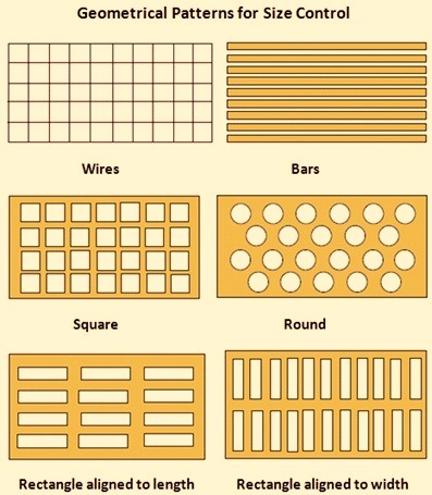
Fig 1 Geometrical patterns for the size control
Screening is the process of separating solids into two or more products on basis of their size. The objective of screening is size control.
The purpose of screening is to separate from a granular substance particles that are smaller than the screen opening from those that are larger. This is not as simple as it sounds, and the difficulties compound as the opening becomes smaller. This can be done dry or wet.
Action of screening is aided when screen is subjected to some kind of motion, reciprocating or gyratory in the horizontal plane, or shaken with a reciprocating motion having both vertical and horizontal components. The minus particles pass through the screen at a diminishing rate until all but the particles closest to the opening size have been separated out. The time duration of the shaking to reach this stage is roughly proportional to the amount of the material on the screen.
The performance of screens falls back on three main parameters namely (i) motion, (ii) inclination, and (iii) screening media. It is measured by the screen efficiency. The most commonly used measure of screen efficiency is the cumulative weight of material that has passed the screen in any time interval, compared to the total weight of undersize in the feed, expressed in a percentage. This can be reversed, when the oversize is the product to be recovered; then efficiency is the weight percent of material in the screened oversize fraction compared to the total weight of oversize in the feed.
The process of screening falls under two categories namely (i) screening by stratification, and (ii) screening by free fall. In the case of screening by stratification, screening is carried out by building up a material bed on a screen deck. The material gets stratified when the motion of the screen reduces the internal friction in the material. This means that the finer particles can pass between the larger ones giving a sharp separation. In case of screening by free fall, the double inclination is used for stratification (from 10-15 degrees up to 20-30 degrees). During free fall, no particle layer can build up on the screen deck and the particles are sized directly via the screening media, giving a higher capacity, (or a more compact installation), but also less sharpness in separation. Free fall screening has optimal use when a large amount of fines is to be removed quickly.
There are a large variety of screens, but these varieties can be reduced usually to four types. Of these types around 80 % used worldwide are of type single inclination, stratification screens. The other types are double, triple or multiple inclination screens, where screening by stratification and free fall are combined for different applications. Single inclination screens are normally circular (15 degree) or linear (0 – 5 degree). Double inclination screens are free fall compact screens with high capacity. They are typical in circuit screening. The triple inclination screens combine capacity and selectivity. They are typical control screen for advanced product fractions. Multiple inclination screens also known as banana screens are effective thin-layer screens. They are popular in coal and metallic ore mining.
Sizing of screens is a time consuming process since various factors influences it and hence it is usually done by the specialists.
Selection of the correct size and type of screen is important. Equally important is the selection of the screening media. This refers not only to a correct aperture related to the cut size, but also to the wear in operation of these screens.
The general rule for the minimum thickness of the screen panel is that it should be one fourth of the maximum feed size. In case panel is thicker, then the capacity, and the accuracy reduces and service life and the blinding tendency increases. The panel thickness is not to exceed the required product size.
Many types of screen panels are used. Tension mats with hooks fits all screens designed with cambered decks and tensioning rails. Bolt down panels are usually pre-tensioned for easy installation and guaranteed screening performance. Wire mesh panels offer superior open area and are quickly available. Self-supporting panels are used for screens of open frame design for tough applications. Modular systems provide flexibility in wear material/hole configuration combinations.
While screening using a geometrical pattern for size control, the types of holes in screen panels are (i) square (the standard choice), (ii) round (for improved service life and coarse screening), rectangle aligned to length (for improved capacity), and (iv) rectangle aligned to width (for improved accuracy and dewatering).
When the screen, supporting a static bed of material of extended size range, is shaken, a phenomenon called ‘trickle-stratification’ causes the particles to stratify from finer at the bottom to coarser at the top. The shaking motion may be in the horizontal plane of the screen, circular or reciprocating, or with a vertical component, or it may be a vibration applied directly to the screen wires.
The probability that any particle will pass a square opening in a woven wire screen is governed by the difference between its average diameter and the opening dimension, and the wire diameter. The probability of a particle passing a square mesh sieve opening, if it approaches at 90 degree to the plane of the opening diminishes exponentially as its diameter approaches the opening dimension. The probability increases exponentially as the wire diameter approaches zero.
This ideal is confounded by unpredictable uncertainties. The necessary turbulence in the material bed caused by the motion of the screen causes inter-particle interference and affects the angle at which a particle approaches an opening. The possibility for a particle to pass the opening without touching a boundary wire is nil. Impact forces from contact with the boundary wires act as impedances to the force of gravity, the only force causing the particle to fall through the opening.
So the motion of the screen, necessary for it to work, also can have the effect of limiting its capacity, in terms of the rate of passage of undersize per unit of area. Different kinds of motion are employed in the design of screening machines, and each has its special characteristics. Most modern screens can be sorted into the following four categories with each are subdivided into a variety of individual differences. These are (i) gyratory screen, (ii) shaking screen, (iii) inclined vibrating screen and (iv) horizontal vibrating screen.
Material factors
Particles in dry bulk materials are found in a variety of shapes, sizes, surfaces, densities, and moisture content. Each condition is to be taken into account when attempting to predict the screen performance, through its effect on capacity in terms of weight passing a given screen opening per unit area. The combined effects on screen performance, or ‘screenability’, of particle shape, surface texture, and surface or internal moisture, are beyond the reach of empirical solutions which are normally based only on size and density, independent of these variables.
The shape of an individual granule may be angular, spherical, acicular, ovaloid, flaky, or slabby. They can be mixed in the same material. Separation cut-point sizes in most screening applications range downward from 100 mm to 0.05 mm. The cut-point defines the minimum particle size retained on the screen, and the maximum undersize particle passing. Unless the particle is acicular, platy, ovaloid or a perfect sphere, it will probably (but not necessarily) be sized by its largest dimension.
For any given shape and size distribution, bulk density of any material is generally directly proportional to its specific gravity. Screening is essentially a volumetric measurement, but capacity, or the rate of passage through the screen, is typically in units of weight per unit time, based on a standard bulk density.
Moisture in granular particles may be absorbed, adsorbed, or both. Either condition can impair screenability, but tolerance is much greater for internally absorbed than for external surface moisture. Surface moisture causes particles to stick together, resisting stratification. Allowable surface moisture for unimpaired dry screening of inorganic granular or pelletized particles ranges from bone dry to 3 %. Absorbed moisture can block the screen openings with cumulative buildups of extreme fines attached to the screen wires.
The size distribution of particles in a granular bulk material is the primary characteristic that governs the rate of undersize passage through a screen opening that is larger than the smallest particle and smaller than the largest particle in a representative sample of the material. Size distribution is measured by sieve analysis, using a series of standardized wire mesh sieves with square openings.
As a general rule, screen capacity at any given level of efficiency, other things being equal, is dependent not only on the size of the aperture, but also on the size distribution.
Machine factors
There are many varieties of screening media (sieve). The most commonly available screen media are made in carbon steel, stainless or other metal alloys, is woven wire screen, made with openings that may be either square or rectangular. Others include profile bars, perforated plates, polyurethane and rubber. The importance of making the best selection of media for any screening application cannot be overstated. The media affects the performance of a screen in terms of capacity, efficiency and cost.
Screening requires relative motion between the sieve and the particle mass. In a few specialized cases the sieve is stationary, but in most screening applications, the particle mass flows over a sieve to which, some kind of motion is mechanically applied. Its velocity determines the volumetric flow rate of the particle mass over the sieve, whose motion is intended to enhance both the flow and the passage of undersize through the sieve. This motion takes several different forms, depending on the design of the screens. It may be (i) circular in the horizontal plane, (ii) gyratory, with a vertical rocking oscillation superimposed on the circular motion, (iii) oscillating in a straight-line, simple harmonic motion, (iv) vibrating with a circular motion in the vertical plane, (v) vibrating with a linear pitching motion on a horizontal sieve having both vertical and horizontal components, or (vi) vibrating only in the vertical direction. In each case, the surface is sloped as required to obtain the desired mass flow, usually at velocities between 10 and 30 metres per minute.
In most designs the screen media, if woven wire, is stretched taut over a supporting frame and the vibration is applied through the frame. The vibration is forced, usually by rotating unbalanced weight(s) driven by an electric motor. For circular motion in the horizontal plane, the unbalance is rotated on a vertical axis. Circular motion in the vertical plane is generated by unbalances rotating on a horizontal axis. Straight-line motion is generated by one or more of a pair of unbalances contra- rotating on horizontal axes. The unbalances are driven by electric motor(s), usually through V-belt transmissions, or in a few designs directly connected to, or mounted on, the motor shaft. These forced-vibration systems are self-balancing, in that the forcing mechanism is an integral part of the vibrating frame which is elastically supported on springs. The tuned spring-mass, or natural-frequency, vibrating conveyor is sometimes adapted, in balanced or unbalanced versions, to screening applications. In a few exceptions, the vibration is applied directly to the screen media mounted in a stationary frame. The vibrating force can be generated by rotating unbalances, or by electromagnetic vibrators.
In most of the designs employing motion in the horizontal plane, the amplitude and frequency (rotation per minute, rpm) are fixed. Amplitudes range from 15 mm up to 40 mm in the oscillating, (straight-line), and up to 75 mm mean diameter in the circular and elliptical designs. Straight-line oscillating motion is generated by one or more pairs of unbalance weights contra-rotating on a horizontal axis. Circular motions are generated by weights rotating on a vertical axis. This axis may be slightly inclined to produce a gyratory effect. Frequency, or rpm, is selected for peak accelerations of up to 3.5 g (9.8 m/sq sec). The axis of rotation may oscillate slightly to produce a gyratory motion. In all but the gyratory designs, the screen surface is sloped slightly to induce or enhance material flow. At a slope of 5 degrees, the force component normal to the surface is a small fraction, about 0.25 to 0.33, of the weight of the particle mass on the surface. This is the distinguishing characteristic of all the horizontal motion designs: the particle mass slides smoothly over the screen without bouncing, providing for the stratified undersize particles the best opportunity to find and pass an opening. The advantage is somewhat diminished by the ease with which an on-size particle can get stuck in an opening, resulting in progressive blinding of the screen. For that reason, these screens must incorporate some means for impacting the screen surface from underneath to dislodge the stuck particles. The most common is the resilient elastomeric (bouncing) ball, supported under the screen by a coarse wire mesh, and contained in groups of three or more within a matrix of confined areas. The random impacts of the balls against the screen prevent the development of progressive blinding. As an additional benefit, the transient local turbulence caused by the impacts improves efficiency by roughing up the smoothly flowing material bed to prevent packing.
Vibrating screens are characterized by motion components in the vertical plane ranging from +/- 3.5 to 6 g or more. The lifting and dropping effect expands the material bed; individual particles are bounced along over the screen with reduced opportunity for finding and passing an opening. This is a disadvantage, compared with the smoother horizontal motion designs. But on the plus side, the strong normal force component acts to eject near-size particles stuck in the openings, thus resisting progressive blinding, and the turbulent expansion of the material bed prevents packing. These advantages gain strength with increasing bed depth and particle size.
The two most common types of vibrating screen are the inclined and the horizontal. In the inclined screen, the single unbalance, rotating on a horizontal axis, generates a circular motion in the vertical plane. Since this motion has no positive transport property, the screen surface is sloped at 15 degrees to 20 degrees to cause the particle mass to travel at velocities of 20 m/min to 30 m/min. The horizontal screen employs a pair of unbalances, rotating in opposite directions on parallel horizontal axes, to generate a straight-line reciprocating motion, inclined to the plane of the screen surface at 40 degrees to 50 degrees. Travel rates on a horizontal surface range between 20 m/min and 25 m/min, and can be increased if necessary by inclining the screen downward at up to about 10 degrees.
Vibrating screen performance can be optimized for any application by changing amplitude (stroke) and frequency (cycles per minute,cpm or rpm). Tests have shown that the screening rate is more responsive to changes in amplitude than in frequency, although higher frequencies are helpful in resisting near size blinding. As a general rule, the amplitude is to increase with particle size, or increased bed depth, and frequency adjusted to maintain peak acceleration in the normal range of +/- 4 to 6 g.
In the special case, where vibration is applied directly to a woven wire screen cloth, creating unidirectional vibration normal to the screen surface, the amplitude is limited by the strength of the screen wires, but frequency is variable, up to about 3600 cycles per minute. The limited amplitude is compensated for with a steep inclination of the screen surface, in the range of 35 degrees to 45 degrees. The screening action is created by the vibration of the screen cloth, which slightly stretches the wires and discourages plugging with near size particles. Such applications are limited to fine screening, with wire diameters less than about 0.6 mm.
The performance of any screen is normally expressed in two variables namely (i) capacity in tons per hour, and (ii) efficiency. These are not independent. Efficiency usually, but not always, varies inversely with loading. The perfect efficiency is said to be 95 %, but this is rarely achieved in actual practice. Normally 85 % to 90 % is more realistic when empirical formulas instead of actual test results are used for predicting screen area requirements.
Screenability is essentially a measure of the rate of stratification of the specific granular material to be separated. Retention time is directly proportional to screen length, at the same travel rate. If the length is doubled, capacity remains unchanged, but the efficiency is increased. Alternatively, if the width is doubled to reduce the bed depth, capacity still remains the same, but efficiency goes up. The screen area is doubled either way, but there is a slight advantage in efficiency from doubling the width while holding the length constant.
Some observations about screenability are as follows.
- Universal ‘rules of thumb’ for optimum depth of bed as a multiple of aperture size are meaningless.
- Retention time for peak efficiency increases exponentially with bed depth.
- The rate of change in undersize removal vs. screen length (retention time), size distribution and bed depth, diminishes rapidly toward zero as length increases. But capacity is always directly proportional to width of a rectangular screen at a given bed depth. This means that in any application with rectangular screens, there is an optimum retention time beyond which capacity at constant efficiency is governed only by bed depth.
- Estimation of screen area requirements based only on empirical formulas, are not a reliable substitute for actual scaled testing. Nuances in material characteristics, and screens differences, both of which significantly affect performance, are unavoidably neglected in the derivation of the empirical formulas.
Estimating screen capacity
Actual scaled testing is the best way to predict screen sizing and performance for a new application. When this is not feasible, or even possible, empirical calculations can provide approximations that are usually better than guesswork. Formulas offered by manufacturers and trade associations are not all the same, and can lead to quite different conclusions from the same input data. Accuracy, in terms of actual vs. predicted performance, is never guaranteed.
The methods described here are subject to the some limitations, but their accuracy is enhanced by their separation into two categories namely (i) coarse screening, and (ii) fine screening. The dividing point is set at 0.25 mm clear opening.
Coarse screening method for estimating screen area requirement for coarse screening applications requires the information namely (i) feed rate to the screen surface, (ii) percent undersize, (iii) screen aperture, (iv) percent half-size in the feed, (v) bulk density, (v) particle shape, and (vi) percent open area of screening medium selected. The screen area is found by dividing the weight of material passing the specified opening by the unit capacity and adjusting for certain factors. These empirically derived factors can be a major cause for differences between predicted and actual performance.
The bed depth is a function of percent oversize, travel rate on the screen, bulk density, and width of screen surface at the discharge.
Wet screening is mandatory when moisture exceeds the limits. During wet screening about 20 % of the volume of water is added in the feed box, and the balance is applied through spray bars spaced at intervals along the length of the screen, with the last bar positioned around 1 m of the discharge. Spray deflectors over drilled holes in the bars spread the water uniformly across the width of the screen, in a thin curtain angled slightly toward the feed end.
Empirical formulas for estimating screen capacities in sizes below 0.25 mm (fine screening) are increasingly unreliable with diminishing particle size. Most of the formulas are approximations derived from a combination of test data, field experience, plain guesswork, and an assumption that the variables are logarithmic functions. Because of the probabilistic nature of the screening process, empirical formulas are no substitute for experience, or scaled test work.
Material traveling over a screen undergoes three different phases, which are generally referred to as (i) layered screening, (ii) basic screening, and (iii) sharp screening. With each phase of the screening functioning differently, a customized screen media approach helps tailor the screen media to each phase accounting for the two most important factors in screen media – open area and wear life.

Leave a Comment