Handling of Hot Metal in Blast Furnace Iron Making
Handling of Hot Metal in Blast Furnace Iron Making
Hot metal (HM) is produced by the reduction of descending ore burden by the ascending reducing gases in a blast furnace (BF). It is liquid in nature and gets collected in the hearth of the BF. From the hearth, the HM is tapped from the taphole of the BF after an interval of time. Normally in large BFs, HM tapping rates of 7 ton/min and liquid tapping velocities of 5 m/sec, in tap holes of 70 mm diameter and 3.5 m long, are typically encountered. The tapping rate of HM is strongly influenced by the taphole condition and taphole length. Generally the temperature of tapped HM varies in the range of 1420 deg C to 1480 deg C.
The tapped HM is handled in the following three stages.
- Handling of the HM in the cast house i.e. from taphole to the hot metal ladles
- HM ladles and their transport
- Processing of HM either in the pig casting machine (PCM) for the production of pig iron (PI) or in the steel melting shop for making steel.
- Capacity of ladles in tons
- Weight of the HM to be handled
- Maximum allowable weight of ladle
- Limiting height of ladle
- Limiting diameter of ladle
- Centre line of trunnion to top of lining flange
- Centre line of trunnion to underside of bottom
- Maximum inside diameter of ladle at top
- Thickness of ladle hooks
- Diameter of trunnions
- Distance between centerlines of trunnions and ladle hooks
- Pouring end platform with railing. It is desirable to have refractory flooring at the platform as the HM may spill over the place.
- Discharge end platform with railing. The discharge end sprocket assembly, strand drive, PI impactor, wagon-spraying unit and discharge chute are mounted on the platform.
- Walkways with railings along the sides of PCM strands (with common middle walkway in case of twin strand PCM).
- Staircases/ladders with railing for reaching the walkways at lower lever and discharge end platform.
Historical development of hot metal handling
During the seventeenth century, the produced liquid iron (usually around 450 kg per cast) from the iron making furnace was drawn into a single trench or ladled into sand moulds to produce domestic products such as pots, pans, stove plates etc. As the BF production increased due to many design improvements, removal of liquid products (iron and slag) became an issue. Production of charcoal BF had increased over the period from one ton to 25 tons per day. This higher tonnage could not be handled with two casts per day through a single trench in front of the tap hole. The cast house contained area for iron casting. The iron removal consisted of a large trench called a trough that sloped downward from the front of the furnace into the sand filled cast house floor. It then spilt into two runner systems. A main runner on each system ran parallel with the length of the cast house. As this runner sloped downhill, a series of dams were made at regular intervals. At a right angle before each dam a smaller runner called a ‘sow’ was formed in the sand. Then off of this sow were numerous cavities called ‘pigs’. These names were applied as this system looked like a line of piglets suckling their mother. There were several parallel rows of sows and pigs produced by pushing D-shaped wooden forms in the moist sand on the cast house floor. During the cast, as each sow and its pigs were filled with liquid iron, the sand dam on the main runner was knocked out with a bar and the molten metal ran downhill to the next sow and pig bed. There were two complete systems which allowed the BF to be cast more frequently. As one side was filled with liquid iron, the other side had its pigs removed and beds reformed.
The iron casting process in the 1880s did not change much from previous operations but pig beds were bigger and in 1909, a slag skimmer was installed to skim the floating slag off of the iron as it flowed down the trough. In 1896, the installation of a PCM invented by EA Uehling finally brought about the complete elimination of the pig bed in the cast house. Next the open top brick lined ladles were introduced. These ladles carried about 10 tons to 100 tons of HM and required the furnace and cast house to be elevated above ground level so that the ladles could be placed under the cast house floor. Though the pig beds have got eliminated but troughs and runners remained and spouts going into the ladles were added to the cast house. In 1915, there was first use of the torpedo type ladles. These railroad mounted ladles carried 90 tons but were increased to 150 tons by 1925.
Handling of hot metal in the cast house
The main trough, iron runner, slag runner, tilting runner and others are employed on the cast house floor to transfer the HM tapped from the BF to HM ladles. The main tasks of the runner system are dispersing the kinetic energy of the stream flowing out of the taphole, the separation of the slag from the HM, and the distribution of the liquid HM into the transport vessels.
Once the taphole is drilled open, liquid iron and slag flow down a deep trench called a HM trough. A block of refractory, called a ‘skimmer’ is set across and into the trough. The skimmer has a small opening underneath it. The HM flows through this skimmer opening, over the ‘iron dam, and down the ‘iron runners’. Since the slag is less dense than iron, it floats on top of the iron, down the trough, hits the skimmer and is diverted into the slag runners. The HM flows into refractory lined ladles. Tilting runner (removable precast runner assembly also known as rocking runner) is generally used for the switching the direction of the HM to second ladle after the filling of the first ladle, in place of conventional fixed runner. The tilting runner is made outside and fixed with temporary fastener for easy joining and removal for maintenance work.
The depth of the trough and runners is to be large enough to accommodate the maximum possible flow of material, allowing for the presence of the refractory lining.
To avoid delay in maintenance work of cast house runner, usually non drainable runner practice is adopted where a certain level of metal pool is maintained continuously between two casting intervals from taphole to skimmer plate.
The runner system is normally fully covered and connected to the cast house dust extraction system, where the front length (around 6 m) of the main trough are uncovered, and the dust is entirely drawn off by a chimney located above it.
Appropriate refractory materials are applied to the respective troughs in consideration of operational conditions. To maintain stable HM transfer and sufficient durability even under severe operational conditions of relatively high productivity coefficients or relatively high iron temperatures, optimal runner materials are used to suit the operation of the BF. The general requirements of the materials for the HM trough and runner are (i) easy to install (appropriate fluidity and hardening time), (ii) corrosion resistance (resistance against slag and FeO attack), (iii) abrasion resistance, (iv) oxidation resistance, and (v) thermal spalling resistance. Generally in the main trough, local wear damage is observed at the slag line (the air/slag interface) and also at the metal line (the slag/metal interface).
The materials used for normal application for the long lining life of the trough are (i) refractories with high silicon carbide content at the slag line for excellent resistance against slag attack, and (ii) spinel material with lower silicon carbide content at the metal line for excellent resistance against FeO attack. Repairs of the BF trough are carried out by wet gunning. The gunning repair is effective to achieve longer durability of troughs, by which the trough maintenance schedule can be optimized. The gunning material is generally characterized by forming a sufficiently dense lining with less water and being suitable for hot gunning even immediately after draining residual HM from the trough.
Hot metal ladles
HM ladles are vessels in which HM is poured for its transportation. There are two types of HM ladles. They are (i) open top ladle, and (ii) torpedo ladle.
HM ladles are lined with refractory brick to keep the contents liquid and protect the outer steel shell. The volatility and erosive nature of HM make monitoring the refractory lining of the HM ladle a vital maintenance function. The consequences of a breakout are considerable, in terms of safety and cost.
Open top ladles are with dished bottom. Important parameters while specifying the open top HM ladle are as follows.
The usual capacities of the HM ladles are of 50 cum, 100 cum and 140 cum. The open top ladle is tilted with a tilting winch or an overhead crane for its emptying.
Open top ladles are mounted on HM ladle cars which are normally designed for rail transportation of HM from BF to PCMs and steel melting shop. The HM ladle car usually consists of (i) bearing frame, (ii) railway carriages, (iii) ladle, and (iv) automatic couplers. Similarly torpedo ladles are mounted on the railway carriages for its movement and are equipped with the automatic couplers.
HM open top ladle cars moves along the railways with the help of traction railway equipment in a train consisting of up to 5 ladle cars. Torpedo ladle cars move usually individually with the help of traction railway equipment and sometimes in a formation of two ladle cars. The two types of ladle cars are shown in Fig 1.
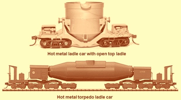
Fig 1 Hot metal ladle cars
Bricks demonstrating refractoriness, resistance to thermal shock and volume stability are used to line the ladle zones. A wide range of refractories bricks are used for the lining of HM ladles. This wide range includes fire clay bricks (alumina content 37 %), high alumina bricks (alumina content ranging from 66 % to 86 %), and alumina silicon carbide bricks. When using alumina silicon carbide bricks, it is necessary to use a layer of insulation bricks for preserving heat since the heat conductivity of silicon carbide is higher than other refractories. For lining of torpedo ladles normally lining is done with zonal concept with slag line refractories, impact pad refractories and roof refractories are selected to suit the parameters existing in these areas. Also the lining of the HM ladles consists of permanent lining and the wear lining.
Castables are utilized in the spout, floor surround and as repair masses. Chemically bonded refractory castables exhibit strength and density combined with volume stability from ambient to elevated temperatures. Monolithics used for lining include mortar, gunning mix and joint mix.
Pig casting machines
HM produced in the BF, whenever not used directly in the steel melting shop or foundry, is cast into PI in the PCM. The HM is solidified In the PCM to small pieces. The PI produced in PCM is in sizes generally of 10 to 45 kg/piece. Such small sizes of PI pieces are produced in PCM by pouring the HM into the mould having small pockets. There the HM is solidified by cooling with air followed by water cooling.
PCMs are designed either for pouring HM from open top ladles or from torpedo ladles. Open top hot metal ladles are normally tilted with the help of a tilting winch. In case of torpedo ladle the tilting arrangement of the ladle is provided on the ladle car itself.
The HM drawn from the HM ladle is poured into a metal transfer launder of PCM for casting into the PI. The metal transfer launder has a fabricated casing, which is lined with refractory. A continuous slope is maintained in the refractory for smooth flow of the HM from receiving point to the discharge point. The launder casing is anchored to the pouring end platform.
There are two usual casting systems namely (i) conveyor belt or strand type PCM, and (ii) wheel type PCM. Strand type PCMs are the most popular machines for the casting of HM into pig iron and are described here.
The body of the PCM consists of four main parts namely (i) machine head, (ii) machine tail, (iii) rollers and link chain, and (iv) device to handle stickers. The machine head has the driving system which is composed of the set of variable speed controlled motor, gear reducer and sprocket. At the machine tail take-up device is provided on the tail sprocket shaft to give appropriate tension to the link chain.
The PCM strand is an endless chain carrying the pig moulds. The strands are placed at an inclination. The level of the inclination is decided on the height required for receiving the HM and for discharging the cast pig iron into the flat cars. The HM is poured in the metal transfer launder of the PCM, through which the HM is discharged into the traveling moulds for casting. The rate of pouring of HM and the take up rate of HM by the PCM are equalized by adjusting the rate of tilting of the ladle and the speed of the conveyor chain of the PCM strand.
The PCM has LH (left hand) and RH (right hand) set of chain links. The chain links are fully machined. These chain links are steel casting joined to each other through a hollow shaft and bushing on which the link can run. Replicable bushes are forced fit to the link and then grubbed for preventing rotating motion between the bush and the link. The LH and RH chain links are assembled on a hollow shaft. At the borehole of the chain, a hardened bush is provided through which the hollow shaft passes through. A rectangular flange is provided to the hardened bush, which engages, the machined housing provided in the chain link. This arrangement maintains the correct relative motion between the sprocket teeth and the chain links and minimizes the wear of the sprocket teeth.
Split pins are provided on the hollow shaft for preventing fall out of the chain links. The chain links travels on the rollers fixed to the technological structure of the PCM. The rollers are spaced such that the chain links remain always supported on the rollers. On the ascending track the rollers carry the load of the chain and the moulds filled with HM whereas on the descending track, the moulds become upside down and the chain gets supported on the bottom rollers on its other side. The rollers are provided with a collar for preventing derailment of the chain. The rollers are mounted on the brackets. Holes are provided at the base plate of the brackets for anchoring the roller assembly to the ascending and descending tracks of PCM. Bearing caps of the rollers are provided with seals for preventing ingress of moisture and atmospheric dust. Protection guards are also provided beyond the bearing caps, which act as a secondary protecting to the system.
Moulds are anchored to the chain at LH and RH links. The chain duly fitted with moulds forms the train. The chain links pass through the sprocket assembly at the discharge end and at pouring end. Motor gear unit drives the sprocket assembly at discharge end whereas the sprocket assembly at pouring end is free to rotate on its bearings. The PCM drive is coupled to the drive sprocket assembly by a geared coupling. The drive for the PCM consists of (i) an AC squirrel cage induction motor, (ii) a pin and bush coupling between motor and gear box, (iii) a helical gear box for speed reduction, and (iv) a geared coupling between the gear box output shaft and the shaft of the drive sprocket assembly. The sprocket assembly at the pouring end is made to float to render compensation for expansion of chain links and for overcoming jams due to external reasons.
A self-regulating tensioning device is provided at the individual sprocket assembly at the pouring end. The tensioning device consists of (i) a fabricated base frame fitted with slide rail, (ii) bearing housing with guide seat matching with the slide rail for the base frame and clevis for connecting the tension rod through pins, (iii) tension rod having one end to connect to the bearing housing through pin and the other end threaded for adjusting the spring tension, (iv) compression springs, and (v) nut to suit the tension rod threading.
A spillage chute is provided below the ascending track of the strand at the location where HM is discharged from the metal transfer launder to the PI mould. The HM spilled at this location due to mismatch of rate of flow of metal and take up rate of HM by PCM, falls on the spillage chute.
A PI knocking device is provided at the discharge end sprocket assembly for quick discharge of the PI iron from the mould. The PI knocking device has a cam and follower mechanism for free fall of the knocker on the cast PI. The PI knocking device mainly consists of a cam disc fitted to the drive shaft of discharge end sprocket assembly. The cam profile is matched to the sprocket teeth for accurate positioning of the knocker and for 100 % repeatability of the striking points. The cam actuates a lever mechanism. A roller moving on the shaft is provided at the end of the lever coming in contact with the cam. The other end of the cam is connected to the shaft of the knocking device. The knocker arm is with one end fitted to the shaft of pig iron knocking device and the other end having a knocker disc. Springs are provided on the knocker arm for absorbing the shock of the impact of the knocker above the tolerance limit.
A PI device consisting of a chain suspended to the technological structure is placed in front of the discharge end sprocket assembly. The purpose of the impact device is to absorb the impact of the pieces of pig iron falling from the moulds at the discharge end. The PI pieces ejected/dislodged at discharge end loose the kinetic energy to the impact chain and fall on to the discharge chute. A discharge chute is placed below the discharge end sprocket for transferring the PI pieces to the flat wagons. A sand cushion is provided at the PI receiving end of the discharge chute for absorbing the impact of the falling PI pieces. The angle of the discharge chute is selected to around 45 deg to the vertical to enable easy transportation / sliding of the PI pieces. The bed of discharge chute is made of rail section, which gives long life and offers minimum frictional force to the sliding PI pieces. The discharge chute is anchored to the technological structure of the PCM strand.
PCM unload the PI into flat wagons which are moved with the help of a winch to the PI area for storage and the dispatch of the PI.
A grizzly is placed below the return track of PCM strand for preventing fall of stickers on to the ground. The first termination point is before the lime splashing unit and the second at about a metre above the ground level near the tail end. A chute is provided at the first termination point for collection of stickers at the ground level. The grizzly is anchored to the technological structure of PCM and an adequate clearance is provided between grizzly and traveling moulds such that stickers cannot get entrenched between them.
A water trough is provided below the PI moulds at the ascending track for collection of the surplus of the cooling water. The trough is connected to the return water pipeline which discharges the water to the return water trench normally running underground and on to the circulating water tank.
Metallic moulds are provided in PCM for the casting of PI. The mould has cavities for dividing the castings into 3 or 4 parts. The mould is designed with varying section thickness to maintain optimum heat transfer during the casting campaign. Two numbers of support brackets are provided in a mould at opposite ends for anchoring the mould to the LH and RH chain of PCM. The support brackets are kept tilted to match the inclination of PCM strand so that the mould surface remains horizontal. The moulds anchored to the PCM chain forms the train. For preventing spillage of metal during pouring of HM in the moulds, the moulds are required to be interlocked with each other. The moulds are thus designed with twin interlocks. When the HM is poured in the moulds, it can get spilled out between the front and rear matching surfaces of the pair of moulds. For preventing such spillage, the rear side of the mould is made in the form of a prism with a reverse tapered bottom surface. The front side of the mould is made with a rising nose. The front side of the rear mould engages the reverse tapered bottom surface with the leading mould making a perfect interlock. When the moulds are being filled up, the HM can leak from either side of moulds, where the anchor brackets are provided. For preventing this leakage ribs, are provided in the moulds and curvatures on either side. The ribs of the preceding and succeeding moulds thus interlock with each other. Overflow notches are provided at the rear side of the mould. These notches limit the filling level of the mould the excess HM cascades to the downstream mould.
The moulds are operational consumable for PCM. The life of the mould depends upon the consistency and uniform filling of mould during casting campaign. In a casting campaign if all the hollow / pockets / cavities of the mould are not filled with the HM and the moulds with hallow pockets / cavities travel upwards, water gets filled up in the empty hollow / pockets / cavities at the water cooling stage of the stand, which causes thermal shocks and can result in the cracking of the moulds.
For preventing sticking of PI to the moulds, the moulds are coated with lime powder. Lime coating is done by spraying lime milk on the interior of the mould during their return passage. Lime powder is slaked before it is discharged into the lime milk preparation tank. The slaking of lime is done in a classifier. The purpose of providing a classifier is to remove the grit continuously from the lime powder and to prepare the slaked lime for its transfer to the lime milk preparation unit. The lime milk preparation unit is a steel tank fitted with an impeller, driven by a motor gearbox unit. Continuous mechanical agitation makes a uniform lime milk suspension, which is pumped to the lime milk splasher unit. A port is also provided in this tank for receiving the return lime milk from the splasher unit. Slurry pumps are provided for transferring the lime milk from the lime milk preparation tank to the splashing tank. The capacity of the slurry pump is selected such that about three times the volume of slurry required for coating the mould can be circulated. The excess quantity is returned to the lime milk preparation unit. Continuous circulation of lime milk between the lime milk preparation unit and the splashing unit, helps in getting a uniform lime milk suspension at the lime milk preparation unit as well as at the lime splashing unit and also avoids sedimentation at any location.
The lime milk splashing unit works on the principle of scooping of lime milk, by continuous rotation of a paddle impeller partially submerged in the lime milk. For this purpose, two discs fitted on a shaft are housed in the fabricated body of the lime milk splashing unit. At the periphery of the disc, are provided the scoops. The speed of the disc is adjusted such that adequate splashing velocities are achieved for coating of time on the cavities of the moulds. The location of the splashing unit is selected such that the return mould remains at adequate temperature for immediate sticking of the lime to it and that the coated mould does not hold any water by the time the mould reaches the pouring end. In some designs of PCMs mould drying facility is provided for the drying of the lime milk on the mould. Gland seals are provided at the exit points of the splasher body to prevent leakage of lime milk at these locations. The paddle shaft is supported on antifriction bearings and is coupled to a motor gearbox unit through a bush and pin type coupling. For the purpose of cleaning and maintenance a manhole is provided at the lower end of the splasher tank. Ports are provided in the splasher body for entry of lime milk and for outflow of the lime milk into the return line of the lime milk preparation unit. Interconnecting pipes and pipe fittings are provided in the lime milk preparation unit and splasher unit for making ring mains. Grating is provided at the topside of the splasher unit to prevent falling of sticker in the tank.
Solidification of HM is achieved in two stages, first stage being natural air cooling and the second stage being direct water quenching. The duration of air cooling is selected such that the top surface of the cast HM reaches a plastic state so that the water spray for quenching can commence without any explosion. The efficiency of the water cooling system is a vital factor, which governs the temperature of the PI pieces discharged from the PCM. The conventional types of nozzles used in spraying of water on the PI has demerit of choking of nozzles because of unavoidable dust / carbon / lime particles getting mixed with the cooling water. The design of the water spraying system is to be such so that it overcomes the problems faced in conventional spraying systems. Normally the water spraying is done through the flute holes provided on the top side of the water runner. A specially designed rotor is provided for adjusting the water flow which has self-cleaning feature in built in it. Two/three circuits of water spray are provided for avoiding pressure drop in cooling water pipelines. Water pipelines are suspended from the technological structure of PCM. Large sized nozzles for flooding of spillage chute are provided. Large size spray nozzles are also provided at the discharge end for cooling of the discharged PI (at the flat wagons).
Regular pipeline connections are provided at the lime milk preparation unit for preparing lime milk. Water distributor is provided near the pouring end platform. The inlet of the distributor receives water from the circulating pump of PCM installed at the pump house located near/above the underground return water tank. The water distributor has two main outlets, first for water cooling of mould / PI and second for wagon spraying. A direct water connection from BF central water supply is desirable for the lime milk preparation unit and for the maintenance water taps points.
The PCM is supported on a technological structure. For convenience of operation and maintenance, following technological platforms, walkways, ladders/staircases and material handling facilities are provided.
Typical specifications for different capacities of pig casting machines are given in Tab 1.
| Tab 1 Typical specifications of pig casting machines | |||||
| Maximum capacity | Machine length | Link pitch | Mould pitch | Speed | Inclination |
| (t/h) | (m) | (mm) | (mm) | (m/min) | deg |
| 100 | 30 – 40 | 300 – 400 | 300 – 360 | 5-15 | 5-15 |
| 150 | 40 – 50 | 400 – 450 | |||
| 200 | 50 – 60 | 450 – 600 | |||
| 250 | 60 – 70 | 600 – 720 | |||
| 300 | Above 70 | 600 – 720 | |||
A typical cross sectional view of a pig casting machine is shown in Fig 2.
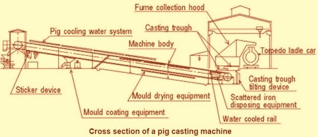
Fig 2 Typical cross sectional view of a pig casting machine

Leave a Comment