Evolution of Blast Furnace Iron Making
Evolution of Blast Furnace Iron Making
The origin of the first smelting of iron is concealed in the unrecorded history of human civilization. The first evidence of iron implements being used in ancient times actually comes from Egypt where an iron tool was found in a joint between two stones in a pyramid. The origin of many prehistoric iron implements was probably meteoric iron. Meteoric iron contains 5 % to 26 % nickel (Ni) while smelted iron contains only traces of Ni and hence iron artifacts made from meteors can be differentiated from objects of smelted iron.
More than 4,000 years ago, people discovered meteoric iron. But it was another 2,000 years before the production of iron from mined iron ore began. The earliest finds of smelted iron in India date back to 1800 BCE (Before Common Era). The smelting of iron is said to have taken place among the Calybes of Armenia, subjects of the Hittite Empire, at about 1500 BCE. When their empire collapsed around 1200 BCE, the various tribes took the knowledge of iron making with them, spreading it across Europe and Asia. The knowledge of ironworking in all of Europe and Western Asia is ultimately traced to this source. The Iron Age began with the discovery of smelting of iron.
Beginning of iron smelting
As with the reduction of copper sulfide ores, the first reduction of iron oxide was probably accidental. It was the powers of observation that led these ancient metallurgists (who were the miners, chemists, and technologists of their day) to realize that iron could be produced in simple furnaces by direct carbon (C) reduction of the oxide ore. The first recorded depiction of a smelting process was found on the wall of an Egyptian tomb dating to about 1500 BCE. (Fig. 1) This process was a simple pit with ore and unknown fuel that had the fire intensified through the use of foot-operated bellows. For the next 3000 years, techniques for the production of iron did not significantly change with iron sponge produced by C reduction of the oxides and iron products made by pounding the sponge.
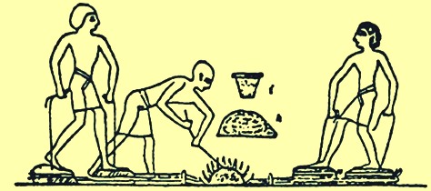
Fig 1 Iron smelting process depicted in Egyptian tomb
Iron oxide ores are present in many areas of the planet earth. Thus, roughly at the same time when reduction of iron ores was taking place in Egypt, it also was being done in other areas. India, China, Africa, and Malaya served as sites for this initial development of iron making practices. It is perhaps significant that the furnaces developed in these countries were all quite similar. There were differences in shape and size, but the furnaces were functionally identical. The chemical reduction to iron occurred without melting, and the resulting metal was relatively pure and soft and was termed wrought iron. It could be hammered into useful shapes. Spears, arrow tips, daggers, and other tools and weapons could be fabricated from this wrought iron.
For about 2000 years, until about the end of the first millennium CE (Common Era), the iron was produced in small local hearths by the ‘bloomery’ process. The size of these structures is not available in the archaeological investigations but a modern reconstruction of a bloomery furnace had internal dimensions of 300 mm dia. x 1000 mm high. In the bloomery process a hearth was constructed and in it was placed multiple layers of charcoal and iron ore until a mound was produced. Around this mound was built a casing of clay and brick leaving a hole at the top for the exhaust gasses and a hole at the bottom for a blast of air produced by operating bellows. The charcoal was then lit and the bellows operated until the charcoal was exhausted. The casing was then broken open, and if the process had proceeded well then there was a pile of spongy iron and a puddle of slag. The hot spongy iron was beaten by hammer to produce an iron billet or iron products. The reactions taking place during the smelting in the bloomery process are described here. The charcoal fire produced carbon monoxide (CO) and the heat drove off water from the bog ore to produce hematite. The CO reduced the hematite to ferrous oxide, wüstite. The CO then reduces the wüstite to elemental iron. The reaction did not go all the way; it proceeded to an equilibrium position and so the resulting gas was a mixture of CO and carbon dioxide (CO2). However, wüstite could also react with any sand to produce iron olivine, (fayalite), which is the major component of the slag produced. This fayalite was a dead end as far as the smelting process was concerned because it could not be reduced to elemental iron under the furnace conditions. The iron produced had a melting point of approx. 1,540 deg C, whereas the slag melting point was at around 1,100 deg C. The temperatures reached were high enough to melt the slag, but not high enough to melt the iron. The process worked well enough, although the remaining slag still contained much iron, often up to and over 60 % FeO (ferrous oxide). The slag was of two varieties, being partly of the open porous nature of bog-ore dross, and partly compact, hard, and very infusible, as obtained from red iron ore.
Developments in iron making process
Improvements in this first iron making process were made by lining the smelting hole with stones as well as mud and using bellows made of wood and leather (Fig 2). In China, the use of iron appeared about 600 BCE, spreading widely during the period 403BCE to 222 BCE. The Chinese developed superior iron making technology and liquid iron was produced as early as 200 BCE based upon the discovery of cast iron utensils. Ancient writings in both China and India refer to iron smelting. Other artifacts include swords, axes, sickles and hoes. By CE 310 a sufficient quantity of iron could be produced to allow the erection of the famous iron pillars of Delhi and Dhar in India. The wrought iron pillar in Delhi is 18 m tall, 410 mm in diameter and weighs 17 tons. In Japan, the traditional iron and steelmaking process known as ‘Tatara’ was not fully developed until the 17th century CE. In North America, South America and Australia, iron smelting was not known to the ancient inhabitants. Iron making technology was brought to these countries by the Europeans.
The iron making process developed around the Mediterranean Sea had spread northward through Europe. The Phoenicians, Celts and Romans helped in spreading iron making technology. One of the iron making techniques spread by the Romans as far north as Great Britain was the early bowl or shaft furnace. This furnace consisted of a bowl-shaped vessel or a cylindrical shaft 2 m high being built into the side of a hill. The air used to fan the fire inside the furnace was provided by an opening built near the bottom of the bowl which faced into the prevailing wind. The furnace was filled through the top opening with layers of charcoal and iron ore that were ignited through the lower opening.
There are two theories on how the iron smelting was driven, one that the wind blasted in through the bottom opening providing air which heated the process and the other that the wind blew over the open top, creating a low pressure area along the inside front wall which sucked air in through the lower opening (Fig 2). In both the cases, the process was dependent on wind and was not reliable throughout the year. The product was once again a mass of sponge iron, which was removed through the lower opening and then hammered into its final form.
Another type of early iron smelter was the beehive furnace (Fig 2). This furnace was constructed on flat ground by piling alternate layers of charcoal and iron ore. The mound was covered with a thick layer of clay and blowpipes connected to bellows were inserted through the lower side walls. The bottom layer of charcoal was ignited and pressurized air was provided by the bellows. At the end of this batch type smelt, the clay dome collapsed. The sponge iron produced was dug out of the demolished beehive furnace for hammering. The production in these furnaces was small lumps of iron and the smelting furnace had to be demolished and rebuilt after each production run.
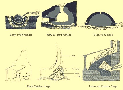
Fig 2 Early processes of iron making
These types of iron making processes were used for several hundred years into the modern era without much improvement. Then approximately during the eighth century, a small forge operating in the mountains of Catalonia in northeastern Spain represented one of the early significant metallurgical advances in iron making. The early Catalan forge (Fig 2) had a stone-built cup called a hearth, about 910 mm high and 760 mm in diameter. A short distance above the front of the base was a small opening that allowed a nozzle known as a tuyere to be installed. The tuyere nozzle was connected to the bellows for the supply of air. The hearth was filled to the tuyere level with lumps of charcoal. Then iron ore was placed above the tuyere and more charcoal was layered on top of the ore. The charcoal was lit and air from the bellows forced hot CO over the ore which reduced the iron ore to a hot, lumpy mass of iron. The mass of iron known as a bloom could weigh up to 160 kg and could be removed from the hearth of the forge with tongs without destroying the stone structure. This quantity of iron could be generated in 5 hours while previous technologies could only produce about 23 kg in 5 hours. The Catalan forge was increased in size over the next 200 years and its use spread into France, Belgium, England and Germany. The sizes of the hearth increased to 1 m square and were built out of rectangular stone blocks. The quantity of air delivered through the tuyere was also increased through the use of an air aspirator known as a ‘trompe’. As water falls through the trompe column, air is drawn into the tube and then expelled at the bottom of the box. When this device was incorporated into the Catalan Forge the pressure of the blast through the tuyere was 0.10 to 0.14 kg/sq cm which was significantly more than a hand or foot bellows could produce. This additional blast pressure accelerated the smelting process and increased the production.
From the 10th century through the 14th century, the Catalan forge underwent further evolution. Hand or foot-operated bellows were replaced with waterwheel-operated bellows and this increased the volume and pressure of the air blast. Next, there were attempts to capture the waste heat from the stack of the forge by increasing the height of the stack and charging iron ore and charcoal from the top of the stack so the ore could be preheated. These furnaces had a stack made of stone masonry that was 1.8 m to 4.8 m high. The stack heights and due to it the heights of the raw material charge could increase was because of the higher pressure of the blast which could be forced up these stacks from the waterwheel operated bellows.
The Stuckofen furnace (Fig 3) which was tallest had not only a 4.8 m high stack but also a change in stack geometry. The furnace took the shape of two truncated cones connected at the widest diameter. Two tuyeres became the standard since the waterwheel drove two bellows with one of them constantly being compressed to deliver blast. There was an opening at the bottom of the furnace to draw off slag but stone work had to be removed to extract the final product which was still a bloom of iron weighing around 318 kg. The Stuckofen furnace could produce 100 to 150 tons in a year which surpassed the production capability of a Catalan forge. One byproduct of this furnace was liquid iron. Because the iron ore had a longer residence time in the furnace to undergo chemical reactions and be exposed to higher temperatures, the iron could absorb more C which lowered the melting point. When the bloom was removed from the furnace, this liquid iron was also removed. At first it was considered a detriment since it was too brittle to be worked with the hammer. In some cases, it was recharged into the furnace or even thrown away as waste. The Stuckofen furnace is considered the forerunner of the modern blast furnace (BF). It was further modified into the ‘Blauofen’ (blow oven) which was capable of producing either liquid iron or forging grade sponge iron at the iron makers’ discretion. This change in desired products was accomplished by changing the amount of fuel charged by 10 % to 15 % and by lowering the position of the tuyeres by 500 mm and pushing them deeper into the furnace. In the 16th century these furnaces were 6.7 m high and could produce around 1.8 tons of iron per day with a fuel rate of around 250 kg of charcoal per 100 kg of iron produced. These furnaces had a life expectancy of about 45 days.
The next step in furnace design to produce liquid iron all of the time was the ‘Flussofen’ (flow oven). The development of the Flussofen or first BF was in the 14th century in the Rhine River Valley and adjacent areas of France, Belgium and Germany. However, with a change in the technology of warfare as well as of iron making, the casting of cannons from molten iron became the dominant industry rather than the forging of swords from sponge iron. As early as 1300 CE, iron makers actively sought to produce liquid iron to cast guns. The first reliable documentation of a known BF is in 1340 CE when the furnace at Marche Les Dames, in Belgium was built. The spread of the Flussofen or BF was relatively slow. The continental nations of Europe are entitled to the credit of having fully developed the BF from the primitive method of producing iron blooms in a Catalan forge. The modern BF is a shaft furnace which was gradually evolved from the Stuckofen and Flussofen.
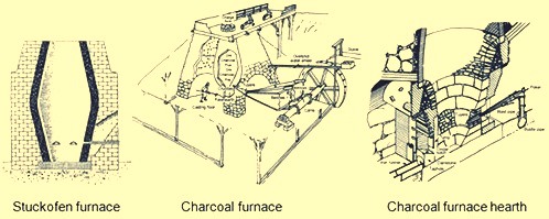
Fig 3 Stuckofen furnace and charcoal furnace
Evolution of charcoal blast furnace
The charcoal BFs (Fig 3) developed in Continental Europe soon spread to Great Britain where the next evolution in iron making technology had occurred. A BF built in Monmouthshire, England in 1565 CE was the first furnace built in the forest of Dean which became a major iron making centre. This BF was 4.6 m high and 1.8 m at the bosh, the widest point inside the furnace where the two truncated cones met. By 1615 CE there were 300 BFs averaging around 2 tons per day per furnace. The rate of growth was so fast that it had caused total deforestation of the land for charcoal production. During the 1600s, statutory restrictions were put to protect remaining forests and many BFs were shut down.
The first BF built in North America was at Falling Creek, Virginia in 1622. This furnace was never put into operation since all of the plant workers were killed and the ironworks was destroyed by the Native Americans. The first successful charcoal BF in North America was in Saugus, Massachusetts, starting in 1645. This BF had a stack which was 6.4 m high with the outer walls sloping inward as they rose and 7.9 m square at the base. The furnace was made of granite and other local stone bonded with a clay mortar. It rested on level ground into which an underground drainage system had been cut to guard against the dampness to which the water that drove its big bellows wheel made it peculiarly susceptible. The BF had a stack with roughly an egg shaped interior and with the maximum diameter known as the top of the bosh was 1.8 m. The bosh, which slopes downward, supported the charge of ore, flux and charcoal. A square crucible called the hearth was below the bottom of the bosh and it was lined with sand-stone (Fig 3). There was an inner wall with sand, clay and rubble between the inner lining and outer masonry which acted as a cushion for expansion and contraction during heating and cooling cycles. There were large and deep arches in the two of the outer walls. Through the smaller arch passed the noses of the two 5.5 m bellows and the two tuyeres, which delivered blast into the BF. Under the larger arch was the working area of the hearth and casting floor. The crucible or hearth acted as the reservoir for the liquid iron. The hearth was 460 mm square at the base but broadened out to 530 mm as it reached its full height of 1.1 m. A projection of its lower portion, called the fore-hearth, consisted of two walls and a forestone or dam. Above, and set back from the dam, was a stone curtain wall, called the ‘tymp’, whose bottom edge came down lower than the top of the dam. Through the opening between the tymp and dam, an operator ladled off the iron for mould casting and with an iron bar, called a ringer, pried away slag that stuck to the walls or accumulated around the tuyere nose. For protection against wear and tear of such operations, both the tymp and dam were sheathed with iron plates. Slag removal was accomplished by raking the liquid material over the dam stone at a location called the cinder notch. To tap the iron however, required the breaking out of a clay plug inserted in a narrow space, called the tap hole, between one of the fore-hearth side walls and one end of the dam.
Besides this complicated masonry work, erection of the BF involved work in timber and in leather. Between the BF top and the adjacent bluff ran a heavy timber structure called the charging bridge. Raw materials were taken in wheelbarrows from their stockpiles on the bluff, across the charging bridge to the top of the BF. On three sides of the BF top were wooden wind screens, set up to provide some safe shelter for the operators charging raw materials into the charging hole that emitted smoke, sparks and occasionally flames. The BF stack at ground level was wrapped on two sides by a wooden lean-to structure called the casting house. This structure provided cover for the trench and mould casting area as well as the bellows. The two bellows were driven in reciprocating fashion by a cam shaft connected to an overshoot waterwheel. The bellows were deflated by the cams on the main shaft and were inflated by counterweights consisting of wooden boxes filled with stones and mounted on the moving beams that extended beyond the casting house roof through holes cut to accommodate them. The BF consumed 3 tons of iron ore, 2 tons of flux stone and 2.6 tons of charcoal per ton of iron produced. The tap hole was opened twice a day and around 450 kg of liquid iron was removed during each cast. The liquid iron was drawn into a single trench or ladled into sand moulds to produce domestic products such as pots, pans, stove plates etc.
The charcoal iron making described above changed only slightly over the next 100 years into the 1700s. The BF stacks increased in size and improvements were made in blowing equipment. A typical charcoal BF of the 1700s had an increased size of 9.1 m height and bosh diameter of 2.4 m. The increase in BF size was possible only through improvements in the wind delivery equipment that resulted in higher blast pressures. The first improvement in blast systems was the invention of wooden blowing tubs which were either be square or round and were similar to wooden barrels held together with external steel hoops. An eccentric crank on the waterwheel had a reciprocating piston rod and blowing tub on each side. The piston inside the tub was fitted with leather to form a seal. As one piston was ascending to compress air in one tub, the other piston was descending in the other tub. At the top of each tub was an outlet pipe connected to a common mixing box that was always under pressure. The mixing box fed compressed air to an air duct or blast main which led to the furnace tuyeres. A typical blowing tub was 1.8 m in diameter and 1.8 m high, producing 0.14 kg/sq cm of blast pressure. The concept of wooden blowing tubs was carried one step further in 1760 by John Smeaton of England. He converted the wooden tubs into cast iron tubs driven first by a waterwheel and then in 1769 by a steam engine. The first BF to use the steam driven blowing engines was built in Scotland in 1769. The invention of steam driven blowing engines had resulted into higher blast pressures which allowed further use of mineral fuels (coke and coal). These improvements of 1700s led the BF production increased to 3 to 5 tons/day by the late 1700s from one ton/day of 1600s BFs. This along with the use of mineral fuels caused a rapid decline in the number of charcoal furnaces in Europe, although charcoal iron capacity increased in North America as the populations moved west where there was vast availability of wood.
In the 1800s, charcoal iron production peaked and then declined. In the middle of the 1800s, high quality iron ores were discovered in Pennsylvania and the Upper Peninsula of Michigan which had dense virgin forests. The charcoal BFs built in this area were the biggest and best equipped. These BFs had stack heights of 13.7 m and bosh diameters of 2.9 m. The number of tuyeres increased from two to three, one each on the three sides of the furnace while the tap hole was on the fourth side. The blowing equipment was usually horizontal blowing cylinders with typical diameters up to 1270 mm and strokes of 1.5 m. Elevator type platform hoists replaced charging bridges and all iron ores and fluxes were weighed as part of a standard charge. Charcoal was still charged by the volume of a large wheelbarrow. Iron shell plates slowly replaced the masonry stone stacks and natural stone linings were upgraded to alumina bricks.
One of the major technological improvements installed on these charcoal furnaces was charging equipment. Originally, raw materials were dumped into an open-mouthed stack through the tunnel head. BF operators realized that an open top furnace had two disadvantages, first the flammable gas leaving the stack could not be captured to fire boilers and second, the distribution of raw materials was causing furnace operating inefficiencies. The first efforts in 1832 in Germany to capture the gas resulted in the installation of a hinged lid over the charging hole which was only opened when the raw materials were dumped from the wheelbarrows (Fig 4). An opening was also placed in the side of the furnace located at the upper stack. This opening was fitted with a pipe known as a down comer that carried the BF gas to the ground level to be burned in auxiliary equipment.
The issue of inefficiency of the BF due to raw material charging needed a more complicated solution which got evolved in several steps. The cause of this inefficiency, described by high fuel rates, was because of fine material being dumped through the charging hole in the centre of the BF remained at the centre of the heap while coarse particles rolled down to the furnace wall. This resulted in higher permeability in the BF periphery and so majority of the gas and heat moved up the walls. This was detrimental to the BF operation as the material at the centre of the BF reached in the bosh area unprepared for melting and at the same time excessive gas flow at the wall enhanced the lining wear. The first attempt to solve this burden distribution problem was introduction of a charging apparatus ‘cup and cone’ (Fig 4). It consisted of an inverted conical cast iron funnel fixed to the top of the furnace feeding the charging hole. This cone was around 50 % of the diameter of the throat. Inside the cone there sat a cast iron cup, which was suspended on a fulcrum beam opposite a counterweight. The cup was raised manually by using a winch connected to the counterweight. This apparatus succeeded in capturing the gas but still a large amount of coarse material rolled to the wall. The next modification to the cup and cone equipment was to hang a cast iron truncated cone inside the furnace (Fig 4). This resulted in moving the peak of raw materials closer to the wall so coarse particles could now also roll to the centre of the furnace resulting into better central permeability and gas flow.
The next evolutionary step in charging which eliminated the cup and cone completely was to hang an inverted cone that opened downward into the furnace (Fig 4). This was the first bell-type BF top. This bell was successful in pushing the peak of wall which reduced gas flow around the periphery and increased gas flow in the centre, but BF gas escaped from the stack with each lowering of the bell. The solution to this was to have a bell and a lid for the charging hole. When material was dumped out of the wheelbarrow, the lid was up but the bell was closed keeping the gas in the BF. Then the lid was closed and the bell was dumped which also kept the gas in the BF and at the same time yielded the proper burden distribution. The results of these improvements were better physical and chemical reaction efficiency inside the BF which reduced fuel requirements, increased productivity and decreased refractory lining wear.
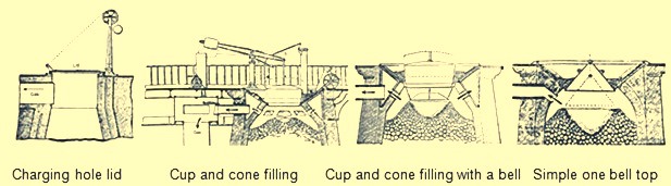
Fig 4 Evolution of BF top equipment
As the BF production increased due to many design improvements, removal of liquid products (iron and slag) became an issue. Production of charcoal BF had increased over the period from one ton to 25 tons per day. This higher tonnage could not be handled with two casts per day through a single trench in front of the tap hole. The size of the cast house building increased to around 12 m wide and 21 m long. The cast house contained separate areas for iron casting and slag removal. The side for iron removal consisted of a large trench called a trough that sloped downward from the front of the furnace into the sand filled cast house floor. It then spilt into two runner systems. A main runner on each system ran parallel with the length of the cast house. As this runner sloped downhill, a series of dams were made at regular intervals. At a right angle before each dam a smaller runner called a ‘sow’ was formed in the sand. Then off of this sow were numerous cavities called ‘pigs’. These names were applied as this system looked like a line of piglets suckling their mother (Fig 5). There were several parallel rows of sows and pigs produced by pushing D-shaped wooden forms in the moist sand on the cast house floor. During the cast, as each sow and its pigs were filled with liquid iron, the sand dam on the main runner was knocked out with a bar and the molten metal ran downhill to the next sow and pig bed. There were two complete systems which allowed the BF to be cast more frequently. As one side was filled with liquid iron, the other side had its pigs removed and beds reformed.
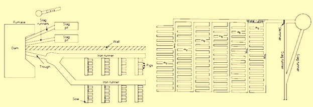
Fig 5 Pig beds in cast house
The other side of the cast house was used for slag removal. Slag was constantly running over the front of the dam down a slag runner and into a slag pit. The slag dam at the front of the BF was divided into two halves with each half feeding a separate slag runner and slag pit. The slag pit was a large depression in the sand with ridges in the bottom. These ridges acted as fracture points when it was time to remove the solidified slag. In some cast houses, a jib type wooden crane was used to lift large pieces of slag. If the cast house operator noticed the slag layer getting too thick, they usually placed a bar in the centre of the liquid slag. Then when the slag chilled around the bar, a rope or chain could be wrapped around it and the large pieces of slag were hoisted by the crane. For slag removal, there were also two complete slag systems so that while one was being used, the other could be cleaned and prepared.
The origin of the word ‘casting’ is understood to have come from the perception that the liquid iron was ‘cast out’ from the furnace. The casting operation comprised of two parts. In the first part, while liquid slag was formed in the BF, it would float on top of the liquid iron until it reached a high enough level to flow between the tymp and dam into the slag runner and to the pit. The second part of the casting was the removal of the liquid iron removal from the hearth of the furnace. This began by shutting off the blast and then driving a pointed bar into the tap hole with a sledgehammer. The liquid iron flowed down the trough into each consecutive sow and its pigs. When the liquid iron stopped flowing, the tap hole was manually plugged with a moist mixture of sand and fireclay or sand and coal. The blast was then returned to the furnace.
After casting, the cast house operators removed the solidified iron from the pig beds. When the pigs were cool enough to handle, they were sent out for dispatch. This cycle was repeated six times per day, with 4-6 tons being produced in each casting. The pig iron produced was classified into different grades. Charcoal iron had a low sulphur value which resulted in a tough gray cast iron which was used to produce rails and railcar wheels needed to support the expanding railways of the 1800s.
The charcoal BFs were discontinued in the late 1800s, since their production costs were no longer been able to meet the competition coming from mineral-based iron making practices.
Iron making based on mineral fuels
Due to the depletion of virgin forests required to sustain charcoal iron making, it became necessary to look for alternative fuel sources. This alternative fuel came in the form of bituminous coal, anthracite coal, coke and even peat. The development of coke and anthracite iron making paralleled each other and coexisted with charcoal production during the 1700s and 1800s. The use of bituminous coal and peat was limited and never became a major iron making fuel. The use of mineral fuel for iron making started from Great Britain, since the deforestation due to charcoal production first occurred there.
In 1708, Abraham Darby leased a small charcoal BF in Shropshire and by 1709 he was producing coke. From 1709 to 1718, coke was mixed with charcoal in increasing proportions in this furnace and in 1718 the BF was using 100 % coke. Till 1750, the three BFs using coke on a regular basis belonged to the Darby family. The use of coke spread during the period 1750 to 1771, with a total of 27 BFs using coke for production of iron. The use of coke increased the production of iron since it was stronger than charcoal. It could support the weight of more raw materials and thus the size of BF could be increased. Coke also improved permeability in the BF, allowing a larger volume of wind to pass through the furnace. This larger volume of compressed air was provided by the steam engine and blowing cylinders.
The use of coke in continental Europe spread slowly. Coke was used in Le Creussot, France in 1785, Gewitz, Silesia in 1796, Seraing, Belgium in 1826, Mulheim, Germany in 1849, Donete, Russia in 1871 and Bilbao, Spain in 1880. In North America, the first use of 100 % coke as the fuel was in 1835 at Huntington, Pennsylvania. However, since 1797, coke was mixed with other fuels in BFs of US.
The efficient use of coke and anthracite in producing iron was accelerated not only by the use of steam-driven blowing equipment but also by the invention of preheating of the air being blown in the BF. In the beginning of the 19th century, it was believed that use of cold blast improved both the quantity and quality of pig iron since it was observed that the production of the BFs was more in winter months and it was erroneously concluded that the lower blast temperature was the reason. But the BF performance improved during the winter months due to the fact that the air was having lower humidity so that more combustion of fuel was supported by a given volume of air blown into the furnace.
In 1828, James Neilson patented his invention of supplying preheated air blast to the tuyeres. The heating equipment was a simple wrought iron box having dimensions 1.2 m x 0.9 m x 0.6 m. This wrought iron box was externally heated. The maximum blast temperature which could be attained with this box was 93 deg C and one box was needed for each tuyere. In 1832, Neilson improved his invention by constructing a larger oven by joined flanges, formed a continuous length of 30 m and provided a heating surface of 22.3 sq m. This oven, which was fired with solid fuel, produced a hot blast temperature of 140 deg C. Since this invention, continuous modification and improvement in the hot blast ovens were made and by 1831, Dixon developed a taller oven with U-shaped pipes that supplied hot blast at 315 deg C. By 1840, about 55 % of pig iron at Great Britain was produced with hot blast.
With the increase in the hot blast temperature, there was decrease in the quantity of fuel needed and increase in the BF production. However the hot blast equipment needed a lot of maintenance. The cast iron pipes supported within a brick oven had different expansion characteristics, which resulted in several cracked pipes. Another issue was that the delivery equipment used for the cold blast, which consisted of solid tuyeres and flexible leather joints between pipes, could not withstand the high temperatures. Another issue with the original hot blast systems was the increased cost of solid fuel to heat the ovens. These issues helped further improvements in hot blast equipment. First, solid fuel used for heating was replaced with BF gas. Initially primitive heat exchanger type hot blast equipment was built on top of the BF and simply used the waste heat to preheat the cold blast running through the cast iron pipes. Then the BF gas from the furnace top was conveyed to the hot blast oven where it was burned to generate heat. This type of hot blast oven became quite complex with numerous rows of vertical pipes. The issue of cracking of the cast iron pipes was tackled by eliminating the pipes and using refractory. For using this method, 2 to 4 stoves were installed for each BF. As one stove was being heated by the burning the BF gas, another was being drained of its heat by heating of the cold blast. In 1854, the Cambria Iron Works was the first plant in the US to use regenerative stoves. The stoves were constructed of iron shells, internally lined with refractory and containing refractories with multiple passages for the blast. A typical stove of this design had 186 to 232 sq m of heating surface. These stoves were representative of those produced by Cowper and Whitwell in 1857. The Whitwell stoves erected in 1875 were 6.7 m in diameter, 9.1 m high and had a total heat surface of 8546 sq m. These were the first stoves to use hexagonal refractory checkers, cast iron checker supports, and a semi elliptical combustion chamber to improve distribution of gas through the checkers. These stoves could supply hot blast to the BF with temperatures of 454 deg C to 566 deg C. This stove design has remained basically the same till date with minor modifications in refractory type, checker shape and stove size.
The other improvement in equipment required by the use of hot blast was the design of the tuyeres and the tuyere stock. The solid cast iron or cast copper tuyeres used on cold blast furnaces were replaced by water cooled tuyeres which were hollow, conical shaped castings which had water circulating through their interior. The pipes from the blowing engines to the tuyeres, which were jointed with leather on cold blast furnaces, were redesigned with metal-to-metal seats. As hot blast temperatures increased the inside of these blast mains and tuyere stocks were lined with refractory, which required an overall increase in size.
The use of hot blast was applied to both coke and anthracite furnaces. As blast pressure increased with new blowing engines, it was found that anthracite could be charged with charcoal to improve the BF productivity. During 1986 the first attempt was made to use anthracite in a cold blast furnace in eastern France. This attempt failed since the ignited anthracite broke up into small pieces and blocked the blast from entering the BF. The evolution of coke iron making and anthracite iron making paralleled each other in the US during the 1800s. In 1826, a small BF was erected in Pennsylvania to operate exclusively on anthracite coal. This practice was unsuccessful both there as well as at other places in the US. During 1833, Dr. Frederick Geissenhainer successfully used hot blast in experiments to smelt iron with anthracite coal. In 1836 the Valley furnace in Pennsylvania used 100 % anthracite and in 1837, George Crane produced 36 tons of anthracite iron per week from one of his BFs at South Wales. David Thomas was the most successful iron maker in using the anthracite in the BF. In 1838 he came to the US and built the Catasauqua BF in 1840 (Fig 6). The furnace was 10.7 m square at the base with 3.6 m bosh and a height of 13.7 m. The hot blast stoves, fired with coal, were capable of heating the blast to 315 deg C. Since this BF successfully produced 50 tons of good foundry iron per week, the furnace was used as a model for the construction of blast furnaces built for using anthracite as a fuel. By 1856 there were 121 anthracite furnaces in operation in the US.
Other fuels were also tried for iron making in the BF. These were peat and bituminous coal. Peat BFs were similar to charcoal furnaces and typically were no higher than 6.7 m. Because the peat was physically weak, the use of these furnaces was located near to the peat deposits and they never played a major role in iron making evolution. Bituminous coal had been used to supplement charcoal prior to the introduction of hot blast. In the 1830s, splint coal was used in Scottish hot blast furnaces. In 1856, there were 6 BFs in Pennsylvania and 13 BFs in Ohio using bituminous coal. The bituminous coal era of iron making was essentially finished by 1895. This method of iron making never became a major force since the coal broke up into small pieces as the BFs were made larger and used higher blast pressure. With coke being the strongest and most available fuel, the evolution of 100 % coke furnaces continued. However there were initial setbacks probably due to low strength coke. By the 1840s coke quality had improved through the use of beehive ovens. In 1867, the ‘Monster’ blast furnace was built at Norton, England. This coke furnace was 25.9 m high, 7.6 m across the bosh and had a working volume of 735 cum. An example of a large coke furnace in the US in 1884 was the Etna furnace located near Pittsburgh. This furnace was 21.3 m high, 6.1 m in diameter at the bosh, 3.4 m in diameter at the hearth and had seven 7 inch (178 mm) tuyeres, three Whitwell stoves and three blowing cylinders that were 2.1 m in diameter. This BF produced 115 tons/day in 1881, 161 tons/day in 1882 and 182 tons/day in 1883. The coke furnace design at this time was very similar to the anthracite furnaces of the same era (Fig 6).
Further evolution of coke blast furnace
The evolution of BFs using 100 % coke continued with major improvements being made between 1872 and 1913. Several technological improvements were made which were centered on the hard-driving BF practice of using more powerful blowing engines, higher blast temperatures, bigger furnaces, better charging equipment, improved raw material preparation and production of clean BF gas.
Blowing equipment design and capacity was a major step to higher production in the hard-driving BFs. Blowing cylinders were replaced with large steam reciprocating blowing engines capable of providing a greater volume of blast air at a significantly higher blast pressure. These blowing engines were of the walking beam, steam condensing type. The steam cylinder’s piston rod was connected to a gallows beam and then by a crank to a heavy, large diameter flywheel. The blowing cylinder’s piston rod was connected to the other end of the gallows beam and each stroke of the steam cylinder provided a corresponding stroke of the blowing cylinder. Cold blast pipes were fitted to each end of the vertically positioned blowing cylinder so that air was compressed on both directions of the stroke. The flywheel provided momentum for the return stroke of the steam cylinder. The air that was compressed in this manner left the cold blast pipes and entered the cold blast main which connected to the hot blast stoves. Prior to this type of blowing engine the normal blast volume was 210 cum/min at a blast pressure of 0.28 kg/sq cm. This blowing engine could produce 456 cum/min at a blast pressure of 0.64 kg/sq cm. Then in 1910, the final major step in blowing engine improvement was implemented in the form of a turbo-blower. The first turbo-blower was installed for the BF of the Empire Steel Co. in New Jersey and was capable of delivering 636 cum/min of air blast. This turbo- blower was the direct ancestor of the modern turbo-blower which can deliver up to 7500 cum/min of blast volume at 4.00 kg/sq cm of blast pressure.
Another major improvement in high productivity BFs was to increase the charging capacity. In the 1870s the BFs were equipped with water driven elevators. In 1883, the first skip hoists were installed. Skips have become larger and faster into the 20th century and existed as both buckets and cars mounted on wheels. In the early 1960s some skip charging systems were replaced with large conveyor belts.
The improvements in furnace charging capacity also included automatic coke charging systems, scale cars in the stock house, two bell tops and the rotating distributor (Fig 6). Automatic stock line measurement was invented in 1901 by David Baker. In 1903, JE Johnson also began to measure top gas temperature and its analysis.
By 1850 as the furnace size increased, the furnace top could be closed. A single bell and hopper arrangement could be used for charging the furnace that kept the top of the furnace closed and sealed. The single bell and hopper system permitted large quantity of gas to escape every time the bell was opened. Soon a second bell and hopper was added above the first so that a gas tight space could be provided between the two bells to prevent the blast furnace gas escaping when the small bell was opened. The upper bell and hopper did not have to be as large as the lower one because several charges could be deposited through it on the lower bell and the upper bell could be closed before the lower bell was opened for dumping the charges in the furnace
Attempts to improve burden distribution occurred in the early 1990s with the McKee rotating top. After each skip of material was charged onto the small bell, the small bell hopper was rotated 60 deg, 180 deg, 240 deg, 300 deg, or 0 deg. This prevented a peak of raw material directly below the skip bridge which had resulted in uneven gas distribution and uneven lining wear. The next attempt to improve burden distribution was done in Germany in the late 1960s. This was accomplished by installing movable panels at the throat of the BF that could be set at different angles for ore or coke. This movable armour has been installed on large numbers of BFs.
The two bell system continued to be the only charging system for the blast furnaces around the world till S.A. Paul Wurth in Luxembourg, developed bell less top (BLT) charging system and the first successful industrial application of BLT charging system was in 1972. This equipment used air tight material hoppers that fed a rotating raw material delivery chute which could be set at numerous angles during the hopper discharge into the furnace. The result was the almost unlimited placement of each material anywhere on the burden surface which allowed the operator to achieve maximum fuel efficiency.
The BLT charging system took over from two bell charging system since it provided a number of advantages to BF operators. During 2003, Siemens VAI introduced Gimbal concept of charging.
Another attempt in the direction of the continuous improvement of the BFs for increasing the production was towards improvements in the cleaning of BF gas. As blast volume and pressure increased at the tuyeres, the velocity and volume of gas leaving the BF top also increased. More flue dust was then carried by this waste gas and if it was not removed, it began to plug up stove checkers which subsequently restricted blast volumes to the furnace. The first step in gas cleaning was the introduction of the dust catcher in the 1880s. With the introduction of the soft iron ores in 1892, the dry-type dust catcher was not sufficient. In 1909, Ambrose N. Diehl introduced a wet gas cleaning system. It consisted of a series of nine high-pressure spray towers and a set of four rotary washers. From 1914 to 1924, several types of tower washers equipped with multiple banks of sprays and baffles were tried at various furnaces. Gas disintegrators which contained high speed rotary drums were also tested in 1907. In 1929 electrostatic precipitators were used successfully at South Works of U.S. Steel. Today, combinations of tower-type gas washers, Venturi scrubbers and mist eliminators are the most common types of gas cleaning equipment.
The newest wet gas cleaning equipment is an annular gap scrubber which cleans the gas as well as controls top pressure. The final result of all these gas cleaning improvements was a decrease in stove checker brick hole diameter with an increase in stove size because plugging with dirt had been virtually eliminated. The resulting increase in stove heating surfaces has ultimately allowed modern stoves to deliver up to 1270 deg C hot blast temperature. The associated top pressure control allowed by modern gas cleaning equipment has resulted in furnace top pressures up to 2.3 kg/sq cm. This higher top pressure in turn increases the density of gases, decreases gas velocity and increases gas retention time in the furnace, yielding better gas-solid reactions, improved reducing gas utilization and lower fuel rates.
Recently, on the newly built and reconstructed BFs, particularly in China, dry cleaning of BF gas by bag filters has found the wide application. Dry cleaning of gas has several advantages over wet gas cleaning using scrubbers and Venturi tubes.
The quest for higher production rates in the late 1870s and onwards forced changes in the size of the furnace size and its configurations. In the 1870s, the furnaces were 22.9 m high. In 1880, the BF size increased to 24.7 m high, 6.1 m bosh diameter and 3.4 m hearth diameter. It produced 120 tons/day with a 1574 kg/ton coke rate. Just ten years later, in 1890, BF was constructed with a stack 28.0 m high and with 6.7 m bosh. It produced 325 tons/day. Then in another 10 years, in 1901, BF was started with similar stack and bosh dimensions as earlier furnace but the hearth diameter was increased to 4.4 m. This furnace produced 463 tons/day at 1113 kg/ton coke rate. The other subtle change with these size increases was the lowering of the bosh/stack bend line and the steepening of the bosh angle. This change was detrimental as the furnaces saw poor burden descent and slipping with these bosh angles. To eliminate these problems, the hearth diameter of these size furnaces was increased up to 6.7 m in 1927. This bigger hearth furnace produced 880 tons/day at a coke rate of 922 kg/ton. The first 1000 ton/day furnace was commissioned in 1929. This furnace was equipped with a hearth diameter of 7.6 m. In 1955, Great Lakes’ A furnace was the largest in the world with a 9.2 m hearth and 24 tuyeres. The next leap in blast furnace size increase occurred during the 1960s as Japan rebuilt their outdated steel plants. Today, furnaces with 15 m hearth diameter, 40 tuyeres and four to five tap holes, are common in Europe and Asia.
Along with the larger furnaces, higher blast temperatures and increasing driving rates, came the need for better BF refractory lining and cooling systems. In the 1880s a high duty fireclay brick with around 40 % alumina and 46 % silica was typical. However, C refractories were used in German BFs since 1886.
While refractory technology was relatively unknown at this time, methods to cool the lining seemed to be the answer to the wear problem. Beginning about 1880, there were simultaneous developments in efforts to maintain furnace linings by means of pipe coils around the bosh or by cooling plates embedded in the brick. One of the first uses of a bronze bosh plate is believed to be an installation made by Julian Kennedy at one of about 1890. An early reference to the use of water-cooled hearth jackets is on the furnace was in 1882. At this time, cooling of the hearth sidewalls and bosh was the concern and stack cooling was not felt to be necessary.
Fritz W Lurman, a well-known blast furnace man of the time opined in 1892 that ‘irrespective of the use of so called refractory materials, the best means of maintaining the walls of the blast furnace is with cooling water’. Coolers with water circulating in them are installed between the shell of the blast furnace and the refractory lining in the upper part of the furnace to protect these components from heat radiation. In addition to having its own coolers, the part of the shell adjacent to the hearth and the bottom of the furnace is also cooled in some furnaces on the outside by water sprays.
Function of blast furnace cooling system is to cool the furnace shell and prevent from the overheating and subsequent burn through. Cooling system removes the excess heat generated in the blast furnace which is otherwise loaded on the shell. Cooling system thus prevent the increase of the shell and lining temperature. Various methods exist for cooling of the shell for the blast furnace. In earlier times, cooling boxes of different size, number and design were used for transferring heat of the furnace to a cooling medium in conjunction with external cooling (spray cooling, double shell). Blast furnaces with cast iron cooling staves are operating since mid-1900s. Cast iron stave cooling was originally a Soviet discovery from where it travelled initially to India and Japan. By 1970s, cast iron cooling staves have attained world-wide acceptance. Since the introduction of these cast iron stave coolers, the development work of blast furnace cooling got accelerated and today a wide variety of coolers are available for the internal cooling of the furnace shell to suit extreme condition of stress in a modern large high performance blast furnace.
The higher charging rates were also wearing out the throat of the furnace faster. In 1872, iron or steel armour was built into the brickwork of the furnace throat at a furnace. Since that time, various types of armour have been used in the stock line area.
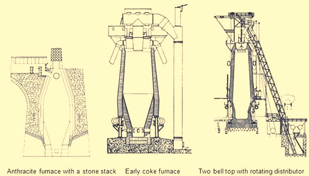
Fig 6 Early blast furnaces
The first important developments in brick making technology did not occur until the 1900s. In 1917, the first machine-made brick was introduced with its resulting increase in density and strength. In 1935, vacuum pressed bricks further improved brick quality. In 1939, super-duty alumina brick containing up to 60 % alumina was first available. In the 1930s, carbon blocks were used in German furnace hearths. Today many varieties of alumina, carbon, and silicon carbide refractories are available for BF lining. The improvements in furnace cooling and lining have increased typical campaign lengths from two years in the 1880s to more than ten years in the 1990s. Today campaign life of BFs has further increased to 20 years.
Another area of the BF which was forced to change with increased production was the casting operation. The old style tymp and dam open front of the furnace was no longer adequate. In 1867, the Lurman front was patented to eliminate the tymp and dam. It consisted of a cast iron panel which was water cooled and had separate openings for iron removal (still known as a tap hole) and for slag removal (known as the slag or cinder notch). This design was changed by the 1880s by rotating the slag notch 90 deg from the tap hole. Both the tap hole panel and slag notch panel were water cooled. By separating these two liquid tapping points, more room was available to set up the furnace for the increasing number of casts required at higher production rates. The area in front of the tap hole was completely available for pig beds while the slag pits were moved around to the side of the furnace (Fig 5). During normal operation, the slag notch was opened with a bar as the liquid slag level approached the tuyeres. The slag was flushed into pits or special slag cars. When the slag notch blew wind out of the opening, it was closed with a manual stopper. By tapping the slag off between iron taps, a greater volume of the hearth was available for liquid iron which resulted in larger cast tonnages. The iron casting process in the 1880s did not change much from previous operations but pig beds were bigger and in 1909 a slag skimmer was installed to skim the floating slag off of the iron as it flowed down the trough.
In 1896, the installation of a pig casting machine invented by EA Uehling finally brought about the complete elimination of the pig bed in the cast house. Next the open-top brick lined ladles were introduced. These ladles carried about 10 tons to 100 tons of hot metal and required the furnace and cast house to be elevated above ground level so the ladles could be placed under the cast house floor. Though the pig beds have got eliminated but troughs and runners remained and spouts going into the ladles were added to the cast house. In 1915, there was first use of the torpedo type ladles. These railroad mounted ladles carried 90 tons but were increased to 150 tons by 1925. Today, the iron ladle design is similar but capacities up to 400 tons are available. Open-type ladles mounted on rail cars are still used today.
Prior to 1890, the tap hole was opened with a bar and sledge hammer. Then in 1890 the first pneumatic rock drill was used. The tap hole was manually stopped with wind off the furnace until 1914 when HA Berg developed the remote controlled mud gun which pushed a clay plug into the furnace with a wind on. In 1906, the first oxygen lancing was used to melt skulls in the tap hole. Modern BFs have evolved to include remote controlled tap hole drills, hydraulic mud guns, cast house slag granulation units and iron tilting spouts to feed an unlimited number of iron ladles. BFs may also have from one to four tap holes and two to six slag pits depending on their size. Removing the bottleneck in the cast house allowed the first 1000 ton/day operation in 1929 and led to 1990s production levels of 12,000 ton/day.
A parallel line of improvement activities which rapidly evolved starting in the late 1800s was iron ore preparation. Iron ore used in iron making consists of many geological forms such as red hematite, specular hematite, magnetite, limonite, fossil ores, bog ores and carbonates. The metallic iron content of these ores ranges from approximately 30 % in the bog ores to 72 % in some hematites. All iron ores are mixed with other compounds in the earth which are undesirable in the smelting process. Beginning in the 1700s, iron ore was roasted with charcoal in open pits or enclosed kilns. The object of roasting or calcining was to liberate all volatile constituents, such as water, carbonic acid or bituminous substances, and to soften and crack the ores, making them more permeable to reducing gases. In the 1800s, iron ore screening was introduced to more closely size the ore for improved gas permeability inside the furnace. At first, hand screening equipment was used but, by the 1870s, steam-driven ore washers consisted of one or two drums that were perforated with holes or slots for the fine material to exit with the wash water while the final sized and washed ore exited the inside of the drum into a wheelbarrow or stockpile.
As iron production increased, the purest iron ores were depleted in many areas so lower grade ores had to be mined. These ores had undesirable impurities and methods to concentrate these ores to higher iron percentages were required. In 1880, Thomas A. Edison obtained a patent for an electromagnetic separator. A demonstration plant was built in Michigan and produced 893 tons of magnetic concentrate in 1889.
Pilot plants to pelletize taconite concentrates were built in 1948. By 1956, two commercial-scale taconite mining and processing operations were producing pellets. The first straight grate pellet machine was made in 1956 and the first grate-kiln pellet machine was put into operation in 1960. Pelletizing technology spread throughout the world from the US. The newest development in pelletizing was the introduction of raw limestone, dolomite or olivine into the pellet to improve its metallurgical properties which, in turn, improved BF productivity and fuel rates.
Iron ore agglomeration also took a separate route from pelletizing earlier in the 1900s. Sintering process originated in the nonferrous industry as a batch process in the late 19th century. Up to the 1950s, most sinter had a basicity ratio of less than 1.0. However, over the next fifteen years, it was realized that a basic sinter with a basicity ratio of more than 1.0 brought a pre-calcined flux source into the BF which resulted in a fuel rate savings.
One of the final technological improvements in iron making over the last 100 years has been tuyere level injectants. The first recorded use of injectant was in 1871 when there was a chilled hearth on the Morgan charcoal furnace. Because blast could not enter the tuyeres due to chilled material, a hole was punched through the furnace wall above the salamander and a large tuyere was installed. Coal oil was then forced under pressure into the tuyere from a pipe running from the top of the furnace. Six days and seven barrels of oil later the salamander had been melted and the furnace was running smoothly. In the first decade of the 1900s early tests with oxygen injection were made in the small BF in Belgium. The first large scale oxygen enriched blast was used in 1951. The benefits of pure oxygen injection are increased BF production due to increased fuel burning capacity and an ability to use more hydrocarbon tuyere injectants. The evolution of hydrocarbon injectant occurred in the 1940s and 1950s. In 1944, William L. Pogue submitted a patent for the use of coal injection. Then in 1953, natural gas injection was implemented. In the early 1960s, injection of oil and tar through lances was developed at numerous steel companies after substantial coke savings were proven by testing in an experimental BF in 1959. By 1967, a large number of the BFs were using some form of fuel (mostly pulverized coal) injection. Today, many BFs use fuel injectants 40 % to 45 % of the fuel rate. The final tuyere injectant, which evolved concurrently with fuel injection, was moisture injection. Historically, hot blast temperatures were limited as excessively high temperature combustion zones resulted in poor burden descent. The injection of moisture consumed coke more rapidly than air alone and produced a gas that was both richer in carbon monoxide and hydrogen and was less dense. These factors improved the rate of heat transfer between gases and solids and the rate of reduction of the burden in the furnace stack, which resulted in a smooth running furnace.
The combination of moisture injection, fuel injection and oxygen injection permitted the increase of hot blast temperature and the use of all of these tuyere level variables further improved productivity and reduced fuel rates in modern BFs.
Evolution of BF iron making as a science
Historically, iron making was more an art than a science. Early iron producers learned their trade through years of training from the previous generation. Many improvements in iron making practice were based on instinct or pure luck. However, by the mid-nineteenth century, science was creeping into the developments in iron smelting.
Charles Schinz of Germany, one of the earliest researchers of chemical and physical phenomena occurring inside a BF, attempted to make quantitative mass and energy balances of BF operation but he was severely limited by the lack of accurate thermodynamic data. He conducted laboratory experiments to determine heat capacity and heats of formation and was apparently the first to determine the reducibility of iron ore. He defined different zones of the BF and the major chemical reactions taking place in each zone. The results of his work were published in 1868.
Several principles which are recognized today were postulated by Sir Lothian Bell, during the late 1800s. He published a book in 1872 which is recognized as the first text book on BF iron making. In 1884, he was seemingly the first to document the function of the different slag components and their effect on melting temperature. He also observed that BF slags are complex structures and there is a range of slag compositions which results in its good fluid properties and desulfurizing capability. His most important contribution was his understanding of chemical reactions. He recognized the importance of CO and CO2, and was the first to start defining equilibrium in the Fe-O-C system. Further, Bell discussed preheating and pre-reduction of iron ores and the importance of the furnace stack where these reactions occurred. He also made carbon, oxygen and nitrogen balances of the BF operations and showed that some of the charged carbon was consumed in the stack by CO2 in the ‘solution loss’ reaction.
A contemporary of Bell was ML Gruner, a professor of metallurgy in France, further expanded Bell’s methods of determining BF heat balances by comparing many different furnace operations. He also believed that the minimum fuel rate for BFs would be achieved when solution loss was eliminated.
JE Johnson, Jr. was the first American scientist to explore the BF process and published two books on BF design and operation in the early 1900s. He applied the first and second laws of thermodynamics to iron making and explained how fuel rate was impacted by blast temperature. He postulated that there was a critical furnace temperature above which a minimum amount of heat is required. This minimum amount of heat he called ‘hearth heat’. In his book, published in 1913, Johnson produced a diagram showing chemical reactions and isotherms in the BF. The application of the critical temperature and hearth heat concepts further convinced furnace operators that the BF process was rational and predictable.
During the period from 1920 to 1930, the flow of solids and gases in the BF was studied extensively by a group of workers named PH Royster, SP Kinney, CC Furnas, and TL Joseph. This group was interested in physical and chemical phenomena occurring in BFs and in order to understand these phenomena they felt it was necessary to sample and probe operating furnaces. Their work started with a small experimental BF and spread to commercial furnaces. The results of their studies showed that the flow of gases and solids was not uniform across any horizontal plane in the BF and that improving gas-solid contact in the stack of the furnace could significantly increase the efficiency of the iron making process. Furnas and Joseph continued this work and determined that raw material size and reducibility was critical in gas-solid reactions. This important work led to the understanding of burden distribution and the optimization of iron ore sizing as it impacts both reducibility and permeability.
In 1962, R. Stephenson explained the role of solution loss. Previously, it had been thought the production of CO by reacting with CO2 and carbon was a waste of fuel. Stephenson pointed out that iron oxide reduction is a combination of indirect reduction and direct reduction and that indirect reduction followed by solution loss is direct reduction. Using these considerations to determine carbon rates for all combinations of these two reduction routes as a function of solution loss, results can be plotted on the ‘carbon-direct reduction diagram’. In the 1960s and early 1970s, the best applications of these BF theories were put into practice in Japan. Currently, the Japanese improvements have spread in the form of large, highly automated BFs to other places.
The theory and practice of iron smelting technology have come a long way in the last 4000 years. The transition from sponge iron produced in forges to liquid iron produced in BFs in the 1300s was the first major step in advancing iron making technology. Then came the change from cold blast, charcoal furnaces to hot blast, coke furnaces in the mid-1800s which brought iron making into the modern era. The better understanding of iron making reactions and improved equipment evolved into the hard-driving furnace operation centered in the 1880s to 1900s. Finally, the revolution in scientific applications to iron smelting, the installation of more sophisticated equipment, and the advent of electronically controlled systems has accelerated BF iron making into the current state as demonstrated by the operation of around 12,000 tons/day BFs with fuel rates less than 460 kg/ton.

Leave a Comment