Breakouts during Continuous Casting of Liquid Steel
Breakouts during Continuous Casting of Liquid Steel
One of the worst catastrophic process failures that can occur during the process of continuous casting (CC) of liquid steel is the breakout of the liquid steel. Breakout occurs when solidifying strand steel shell ruptures or tears beneath the mould. There are several reasons due to which the solid shell of the strand breaks and allows the still liquid steel contained within it to spill out and damage the equipment of CC machine.
A breakout is the most detrimental incident associated with the process of continuous casting. This incident is not only very costly but is also a serious safety hazard for the operators of the CC machine. Breakout leads to a shutdown of the strand and results in the loss of production time along with significant drop in the yield. Hence each breakout causes a significant direct economic loss. For the restoration of the CC machine strand, it typically requires an extended turnaround involving removal of the spilled steel material from within the strand equipment and/or replacement of the damaged part of the equipment.
Breakouts can be avoided by reducing the casting speed thereby providing more residence time in the mould for the steel to solidify. To avoid the occurrence of a breakout, it is critical to detect improper solidification of the steel shell in advance with enough lead time to appropriately slow down the CC machine. A number of approaches have been adopted to predict breakouts in the continuous casting process.
A breakout is normally due to the steel shell wall being too thin to support the liquid steel column above it. This is caused due to a condition which has several root causes often associated with the management of heat transfer. Improper cooling water flow to the CC mould or disturbance in the strand cooling water spray system can lead to inadequate heat removal from the solidifying liquid steel, causing the solid shell to thicken too slowly. If the withdrawal rate of the steel in the strand is too fast, the shell may not have sufficient time to solidify to the required thickness even with enhanced cooling sprays. Similarly, the incoming liquid steel may be too hot and the final solidification may occur further down the strand at a later point in the mould than expected. In case this point is below the straightening rolls then the shell may break due to the stresses which are applied during straightening.
A breakout can also occur as a result of physical irregularities or damage to the steel shell occurring within the CC mould during the initial period of solidification. Excessive turbulence within the CC mould can cause an irregular shell pattern that grows abnormally. It can also entrap slag droplets or scum within the steel shell which reduces the wall strength.
A common occurrence is the sticking of the steel shell to the CC mould’s surface and its tearing. The steel shell constrained by the CC mould ruptures at the meniscus portion, and the liquid steel flows out of the ruptured portion immediately under the CC mould. This type of breakout is called sticker breakout. Modern CC moulds having several instruments and computer control systems typically detect the sticking in the mould and slow down the casting speed temporarily to let the wall refreeze and heal while it is still supported in the CC mould. Should the tear occur near the exit of the CC mould or be of unexpected severity, the steel shell may still fail in a breakout once it emerges from the CC mould wall. Sticker type of breakouts is the major type of breakout during the continuous casting operations. One of the reasons of sticker breakout is the poor lubrication in the mould. Fig 1 shows propagation of sticking in the mould leading to a breakout.
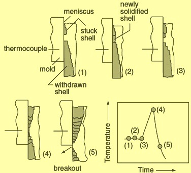
Fig 1 Propagation of sticking in the mould leading to a breakout
Cracks are also the reason for breakouts. In case of breakouts due to the cracks, the thin portions of the steel shell caused by the delay of solidification in the cast steel corners or oscillation marks rupture immediately under the CC mould.
Another reason for breakout is scum entrapment. In this case the thin portion of the steel shell caused by the delay of solidification due to scum entrapment rupture immediately under the CC mould.
As the continuous casting process has progressed and got matured, the distribution of the types of breakouts changed dramatically from heat transfer related phenomenon to the present day predominance of mould sticking. The percentage of the sticking type of breakouts to the total number of breakouts is normally in the range of 75 % to 80 %. The percentage of the breakouts due to the cracks usually ranges from 15 % to 20 % while the percentage of the breakouts due to slag and scum entrapment is usually in the range of around 5 %.
While continuous monitoring of mould heat removal can provide an effective means of detection of the development of breakout conditions, the response time is normally insufficient to indicate a rapid happening phenomenon of steel shell ripping and tearing.
If the incoming liquid steel is severely overheated (very high superheat) then it is preferable to stop the CC machine than to risk a breakout. Also liquid steel with contamination of lead (Pb) can form a thin film between the CC mould wall and the steel, inhibiting heat removal and growth of steel shell thus increasing the risk of breakouts.
CC mould hot phase temperature is critical since it has been seen that when hot phase temperature exceeds 350 deg C then strand to copper sticking occurs. Further in today’s high productivity CC machines routinely exchange of tundishes and submerged entry nozzles ‘on the fly’ is the normal practice during normal operations. These transient operations inevitably lead to unstable periods of casting speeds and mould level control. During these periods, the process of mould lubrication is severely strained and enhances the probability of sticking.
In case of certain grades of steels (for example high carbon steels) which are usually cast at lower temperatures due to their lower liquidus temperatures, sticking is often associated with the poor performance of the casting powders. This is also true for those grades of steels which are to be cast at lower speeds due to the metallurgical reasons.
The task of detection and prevention of breakouts during the continuous casting operation is as old as the continuous casting technology itself. For this purpose several measurement methods have been developed and used. These consist of measurements of temperature, friction force, withdrawal force, vibration and structure borne noise level. Out of these methods measurement of temperature by means of thermocouples at the mould copper plates is the most reliable and the preferred method.
Control systems to effectively reduce the frequency of breakouts were developed by installing instrumentations in the CC moulds. Initially these instrumentations were based on mould water differential temperatures. This method was later refined by calculating mould heat transfer relationship using the mould water data. However with this detection was limited to breakouts caused by a progressive decline in heat removal.
Later when sticking induced breakouts increased and became predominant, systems based on more direct techniques were developed. In these techniques mould/strand friction is measured with accelerometers, load cells, and strain gauges. These systems successfully detected some of the sticking incidents but these systems also gave some false alarms.
The systems were further modified for localized thermal monitoring with heat flux sensors (embedded thermocouples). These systems have proven to be more effective method of detecting and preventing sticker breakouts. It is seen that the thermocouple based sticker detection in combination with eddy current mould level detection provides high break out safety even at high casting speeds.
Presently the focus has shifted and it is no longer exclusively on early detection of breakouts but also on monitoring of the heat dissipation and the contact between the steel shell and the CC mould. It is therefore not unusual for individual CC moulds to be equipped with a large numbers of thermosensors. This large number of sensors need good amount of cabling and coupling and hence need substantial investments. Also it results into considerable maintenance expenses.

Leave a Comment