Billet Inspection and Conditioning Facilities
Billet Inspection and Conditioning Facilities
A considerable percentage of steel bars and wire rods are used for the safety-related parts of automobiles after undergoing post-processing steps (secondary and ternary processing). Quality requirements for these steel bars and wire rods are becoming increasingly diversified in consideration of the workability at the stage of secondary and ternary processing and the use conditions of the machine parts into which they are made. In addition, the need for quality assurance throughout the entire length of the steel bars and wire rods has also increased, and the steel plants are required to apply very severe quality standards for meeting these requirements. Due to this reason, the importance of the reliability of inspection and conditioning of billets which is the starting material for the production of steel bars and wire rods has increased significantly.
Depending on the application, billets require surface inspection and conditioning to minimize the surface imperfections. Standard inspection methods consist of visual inspection of the billet surface under white light conditions or wet magnetic particle inspection under black UV lighting. Normally steel plants shot-blast the surface of the billet to remove the mill scale and to improve the visibility of the surface, depending on the type of surface conditions they are trying to detect. The surface imperfections are normally marked as they are detected, and these locations are conditioned. Methods employed are usually machine- grinding and sometimes scarfing.
The traditional inspection techniques (other than visual method), which have been aligned to the rolled billets, are all conditioned to the detection of defects which have a significant length component, i.e. seams, rolling laps, tonguing, etc. Continuously cast billets contain, on the other hand, a completely different type of defects such as pinholes, corner tearing, reciprocation marks, entrapped scum, teeming arrests, double skins, and laps etc. These defects need different type of inspection equipment since the inspection techniques used in the inspection equipment designed for inspecting rolled billets are of little use for the detection of the new type of defects.
Inspection and conditioning of billets play very decisive roles in the quality assurance of the bar and wire rod products, because a small surface defect of a billet gets elongated during the rolling and becomes an extensive product defect, requiring a considerable cost for conditioning and making quality assurance in all the product length difficult. For this reason, it is necessary for a steel plant to take necessary measures to improve the defect detecting capability during the billet inspection and conditioning process by using mechanized and automated inspection and thus eliminating the human sensory errors during the inspection.
A billet inspection and conditioning line mainly have the facilities comprising (i) billet receiving, (ii) roller tables for billet movement, (iii) shot blasting machine for cleaning the billet surface, (iv) billet straightening facilities, (v) billet inspection facilities, (vi) automatic billet grinding machine, (vii) billet manual grinding facilities, (viii) billet cutting facilities, (ix) billet marking, and (x) grid for billet removal. The billet inspection and conditioning line is to satisfy the following requirements.
- Operate in full integration with and guarantee constant tracking of material incoming from stock or directly from the continuous casting machine, throughout the whole conditioning process, up to the billet removal from the line.
- Carry out a primary conditioning by shot blasting to remove mill scale and to remove some of the surface defects of low depth and at the same time provide billet surface with finishing and appearance suitable to be inspected.
- Ensure accurate inspection before conditioning in order to not miss any defects
- Provide a modern infrastructure and working station, with user friendly interface for inspection, so that the activity can be performed in a safe and comfortable area excluding the necessity to have the operator inside the equipment area.
- Assure a reliable record of defects data, precise and effective transmission to the grinding unit in order to perform full automated conditioning cycle.
- Guarantee the minimum material removal, closest as possible to the effective areas where defects are and, by doing this, guarantee also a reduction of the production costs of both utilities (e.g. electricity) and consumables (e.g. grinding wheels).
- Provide hardware and software tools to interface with any continuous casting quality monitoring system for the purpose of exchanging information and improving cycles and productivity by the implementation of predictive analysis practices.
- Being able to operate within a wide range of surface temperatures in order to receive the benefit, at grinding stage, of higher metal removal rates.
In the modern billet inspection and conditioning lines which are using mechanized and automated inspection, defects which are detected are marked on the surface at the exact position where they occur by automatic paint spraying. Billets with surface or interior defects which exceeds the tolerances, can automatically be sorted out for repair. Billets can also be automatically sorted out according to length criteria.
The modern in-line inspection system for surface defects makes it possible to detect defects with a high degree of accuracy, and with high reliability according to criteria which normally varies with the intended final use of the steel bar and wire rod products. The inspection criteria are chosen in such a manner that the product satisfies the quality requirements of the customer with respect to defect tolerances, bearing in mind that surface in-homogeneities without significance for the further preparation of the material, are not be detected.
Inspection techniques
There are several inspection techniques (Fig 1) which can be employed and these are described below.
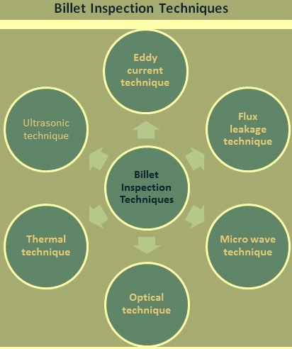
Fig 1 Billet inspection techniques
Eddy current techniques
These are well established for rolled products at normal and high temperatures. The engineering problems obviously increase at elevated temperatures because of the closeness of the detector to the test material. However, they have been overcome since the systems are in common use at rolling temperatures.
The application of eddy currents to continuously cast billet inspection makes it necessary to consider an inspection interval or pitch of the order of 1 mm to 2 mm to cater for the pinhole type defects. A common method of applying eddy current probes in billet surface inspection relies on the use of a high speed disc which is positioned above the billet surface. If it is assumed that six probes can be accommodated in the disc then a rotational speed of 6,000 rpm to 12,000 rpm is necessary to obtain an inspection pitch of the order of 1 mm at a billet longitudinal speed of 0.5 m/s to 1.0 m/s. To obtain sufficient probe resolution, small sized probes are to be employed which in turn requires small operating clearances of the order of 1 mm to 2 mm. It can be seen therefore that this method has a number of technical problems and also it is insensitive to defects which are transverse to the billet length. The resolution of pinhole defects also remains in doubt.
An alternative approach is to use arrays of eddy current probes housed in a block and supported above the moving billet surface. This arrangement is sensitive to transverse face cracking, reciprocation marks, double skins, slag/scum patches and teeming arrests. It therefore forms a useful tool for the inspection of a range of continuous casting defects but the detection of pinholes still present a problem.
A trailing eddy current probe can also be effective in identifying transverse corner cracking and to a lesser extent longitudinal corner cracking.
Flux leakage techniques
Magnetic particle inspection system based on flux leakage techniques is a well proven system but only suitable for cold billets. The magnetic sensors are deployed either to scan the surface directly or indirectly where a contacting tape transfers the magnetic image to a separate scanning head. In either case there is a temperature limit imposed on the billet to ensure a satisfactory test. Attempts have been made to utilize this form of inspection on continuous cast billet and the results are very disappointing. Continuous cast defects such as pinholes, transverse cracking and other defects with a transverse component can escape detection and in addition the level of spurious marking is very high. It is important to remember that the level of spurious marking generated by any inspection system is just as significant a feature as its detection efficiency.
The scanning interval already discussed under the eddy current technique section is equally applicable in this case since generally mechanical means are used to create a transverse scanning pattern. This approach therefore is considered to be inappropriate to continuous cast billet.
Microwave techniques
This inspection technique is fairly new in its concept and whilst it has been applied in a few very specific applications in a laboratory environment. The proposed application of the technique to in-line inspection of the billets in a steel plant is thought to be unique. The detector can be mounted some tens of millimeters away from the billet surface and that must be of benefit since it reduces its susceptibility to mechanical damage. The inspection area is, however, relatively large and therefore one is to expect that it is responsive only to large area defects or to cracks of either longitudinal or transverse orientation.
This form of detector shows enough merit to be considered but the capital cost of each detector head is high.
Optical techniques
These offer an easier solution from the engineering point of view because the detectors can be positioned well away from the surface of the material and it is possible to examine the full length of the product at normal line speeds.
One major disadvantage of the optical technique based systems however is their inability to discriminate on the basis of depth or severity of defects. Differentiation is on the basis of whether a black or white image is present. Signal processing of the video information is therefore necessary to establish a pattern which could be recognized as being consistent with the various defect types. It is also necessary to provide a high intensity continuous light source to achieve the requisite illumination intensity.
Thermal techniques
Considerable effort has already been expended to extend the application of thermal or infra-red cameras to the inspection of billet at rolling temperatures. Several techniques utilizing emitted radiation and/or superimposed reflected radiation in various combinations have been used and include colour synthesis. The ultimate aim is to allow control of hot rectification processes on-line before further processing without cooling. The results of these developments have been varied but the overriding feature has always been that the defects are to be quite large to ensure detection and this feature makes these techniques inappropriate.
Recently a more refined thermal inspection system has become available and is marketed by Elkem under the name of Thermomatic. This system has been developed for billet inspection and contains a means of inducing thermal energy into the billet surface in a controlled way. The surface is then viewed with a sensitive infra-red camera and the thermal images are correlated to allow identification of longitudinal seams. The range of billet temperature is, however, strictly limited and the system is insensitive to defects with transverse orientations. This obviously limits its application for continuous cast billet.
Ultrasonic techniques
This technique is poor in terms of defect resolution because of the obscuration by scattered waves from other defects. It is necessary to consider the use of surface waves to identify surface defects and with conventional methods the provision of a suitable couplant at the normal billet speeds and temperatures is normally problematical. Also the generation of surface waves requires good control over the entry angle and with the types of surface condition commonly experienced with continuous cast material this is usually in doubt. An alternative approach to overcome these coupling problems is to resort to the use of electromagnetic methods but this still is subject to the limitations of defect detection as already described under flux leakage techniques.
Selection of inspection techniques
As described above, it is seen that three methods of inspection are more useful for continuously cast billets than others. They are (i) optical techniques, (ii) microwave techniques, and (iii) eddy currents techniques. The optical system with correct illumination levels is capable of resolving the smaller defective areas such as pinholes, which most other methods have difficulty in identifying. It is also capable of responding to other types of defects which show up in relief under the incident lighting conditions. The microwave system has the benefit of reasonable operating clearances (of the order of 30 mm) and usually resolve large area defects and, both longitudinal and transverse cracks of the order of 10 mm or more in length. Reciprocation marks and teeming arrest marks also generate significant responses. The eddy current probe array on the other hand have to be positioned closer to the surface, at say 3 mm, but is capable of better resolution in the detection of transverse cracks, teeming arrests, reciprocation marks, etc. than the microwave technique.
Billet conditioning facilities
The principle contradiction of surface conditioning by grinding or other technologies is that the required quality is produced on the one side and yield loss is created on the other. The objective to run the process in the most economical way therefore has to be to provide the surface quality required and to minimize the yield loss at the same time.
The common practice today in many steel plants is still the grinding of the full surface based on empirical data of defect position and depth. Though the billets might be inspected by rather unreliable detection systems, full surface grinding often is applied to be on the safe side in order to remove all the defects, especially for high quality grades.
The economic efficiency can be reached if the cracks can be identified and removed selectively. The billet inspection system with automatic camera identification provides a unique solution for the reliable and reproducible recognition of cracks in any direction. Moreover the position of cracks can be stored and the data can be forwarded to the downstream grinding machines.
The cracks identified by the billet inspection system are shown on a display unit arranged in the operator’s cabin of the grinding machine. The movements of the grinding table, where the billet is attached to, are synchronized with the display unit. The operator uses the machine’s joysticks to approach and grind the cracks. To examine if the crack has been successfully ground, a special lighting system supports the operator with the visual checking. This combination enables the manual selective grinding of defects but also the full surface grinding if the rate of defects exceeds a limit to be defined. An initial decision of the applicable grinding method is made by the crack detection system and relayed to the operator, who can accept or override the system’s choice.
In case of automatic inspection and grinding system, the crack coordinates determined by the crack detection system can be forwarded to the grinding machines control system to grind the cracks automatically. The grinding machine approaches the cracks in both longitudinal and transversal billet direction with the coordinate data and carries out the grinding task. The operator’s task is only to supervise the process.
The successful removal of cracks can be controlled automatically by using the crack removal detection system, a combination of industrial camera, special lighting and adapted software. This combination provides the highest level of automation with the ability to partially grind the cracks or fully grind the surfaces as well as the round corners of the billet.
The material tracking system required for an automated operation process also provides the possibility to record and store the result of the inspection and the subsequent grinding process as the history related to each billet. The billet conditioning can then be part of an integrated quality management system through the whole production process until the final product and application. Another advantage recording the inspection data of each billet is that the data can be related to the upstream production process.

Leave a Comment