Basics of Hydraulics and Hydraulic Systems
Basics of Hydraulics and Hydraulic Systems
Hydraulics is the generation of forces and motion using hydraulic fluids which represents the medium for the transmission of power. Hydraulic systems are extremely important for the operation of heavy equipments. The word ‘hydraulics’ is based on the Greek word for water and originally meant the study of the physical behaviour of water at rest and in motion. Today, the meaning has been expanded to include the physical behaviour of all liquids, including hydraulic fluids. Hydraulic systems are not new to the industry. They have provided a means for the operation of many types of industrial equipments. As the industrial equipments have become more sophisticated, newer systems with hydraulic power are being developed.
Hydraulic systems are used in modern production plants and manufacturing installations and they play a major role in steel industry, mining, construction and materials handling equipment. Hydraulic systems are used to operate implements to lift, push and move materials. Wide range of applications of hydraulic systems in the industry has only started since 1950s. Since then, this form of power has become standard to the operation of industrial equipments. Today hydraulic systems hold a very important place in modern automation technology. There are many reasons. Some of these are that hydraulic systems are versatile, efficient and simple for the transmission of power.
Transmission of power is the job of the hydraulic system, as it changes power from one form to another. In hydraulic systems, forces that are applied by the fluid are transmitted to a mechanical mechanism. To understand how hydraulic systems operate, it is necessary to understand the principles of hydraulics. Hydraulics is the study of liquids in motion and pressure in pipes and cylinders.
The science of hydraulics can be divided into two branches namely (i) hydrodynamics, and (ii) hydrostatics. Hydrodynamics deals with the moving liquids. Examples of the applications of hydrodynamics are water wheel or turbine; the energy that is used is that created by the motion or water and the torque converter. Hydrostatics deals with the liquids under pressure. Examples of the applications of hydrostatics are hydraulic jack or hydraulic press and hydraulic cylinder actuation. In hydrostatic devices, pushing on a liquid that is trapped (confined) transfers power. If the liquid moves or flows in a system then movement in that system happens. Most of the equipments based on hydraulics in use today operate hydrostatically.
The three most commonly used technologies for in context of control technology for generating forces, movements, and signals are hydraulics, electricity, and pneumatics. The advantage of hydraulics over other technologies is given below.
- Transmission of large forces using small components which mean great power intensity
- Precise positioning
- Hydraulic system delivers consistent power output which is difficult in pneumatic or mechanical drive systems
- Startup is feasible under heavy load
- Even movements are possible independent of loads, since liquids are scarcely compressible and flow control valves can be used
- Smooth operation and reversal
- Good control and regulation
- Favourable heat dissipation
- Possibility of leakage is less in hydraulic system as compared to that in pneumatic system
- Ease of installation, simplification of inspection and minimum of maintenance requirements
- Hydraulic system uses incompressible fluid which results in higher efficiency. it has only negligible loss due to fluid friction
- The system performs well in hot environment conditions.
The disadvantages of hydraulic systems include (i) pollution of the environment by waste oils (danger of fire or accidents), (ii) sensitivity to dirt, (iii) danger from excessive pressures (severed lines), and (iv) dependence on temperature (change in viscosity).
There is a basic distinction between stationary hydraulic systems and mobile hydraulic systems. While mobile hydraulic systems move on wheels or tracks, the stationary hydraulic systems remain firmly fixed in one position. A characteristic feature of mobile hydraulic systems is that the valves are frequently manually operated. In the case of stationary hydraulic systems solenoid valves are normally used.
Typical application areas of the mobile hydraulic systems include (i) construction equipments, (ii) tippers, excavators, elevating platforms, (iii) lifting and conveying devices, and (iv) yard material handling equipments. The main application areas of the stationary hydraulic systems are (i) production and assembly machines of all types, (ii) transfer lines, (iii) lifting and conveying devices, (iv) rolling mills, (v) presses, (vi) lifts, and (vii) injection moulding machines etc. Machine tools are a typical application area.
In the seventeenth century, a French scientist named Blaise Pascal formulated the fundamental law which forms the basis for hydraulics. Pascal’s Law states that ‘pressure applied to a confined liquid is transmitted undiminished in all directions, and acts with equal force on all equal areas, and at right angles to those areas’. This principle is also known as the laws of confined fluids. Pascal demonstrated the practical use of his laws and demonstrated that applying a small input force against a small area can result in a large force by enlarging the output area. This pressure when applied to the larger output area produces a larger force. It is a method of multiplying force.
Multiplying of the forces is only one advantage of using hydraulic fluid to transmit power. Further the forces do not have to be transmitted in a straight line (linearly). Force can be transmitted around corners or in any other non-linear fashion while being amplified. Fluid power is truly a flexible power transmission concept. Actually, fluid power is the transmission of power from an essentially stationary, rotary source to a remotely positioned rotary (circular) or linear (straight line) force amplifying device called an actuator. Fluid power can also be looked upon as part of the transformation process of converting a kind of the potential energy to an active mechanical form (linear or rotary force and power). Once the basic energy is converted to fluid power, there are other advantages as given below.
- Forces can be easily altered by changing their direction or reversing them.
- Protective devices can be added that allows the load operating equipment to stall, but prevent the prime mover from being overloaded and the equipment components from being excessively stressed.
- The speed of different components on equipment can be controlled independently of each other, as well as independently of the prime mover speed.
Hydraulic fluids
Hydraulic system fluids are used primarily to transmit and distribute forces to various units to be actuated. Liquids are able to do this because they are almost incompressible. Water is unsuitable as hydraulic fluid since it freezes at cold temperatures and boils at 100 deg C and also since it causes corrosion and rusting and furnishes little lubrication. Most hydraulic systems use oil (hydraulic fluid), because it cannot be compressed and it lubricates the system. Many types of fluids are used in hydraulic systems for a variety of reasons, depending on the task and the working environment, but all perform the following basic functions.
- The fluid is used to transmit forces and power through conduits (or lines) to an actuator where work can be done.
- The fluid is a lubricating medium for the hydraulic components used in the circuit.
- The fluid is a cooling medium, carrying heat away from the “hot spots” in the hydraulic circuit or components and discharging it elsewhere.
- The fluid seals clearances between the moving parts of components to increase efficiencies and reduce the heat created by excess leakage.
Some of the properties and characteristics that must be considered when selecting a liquid as satisfactory hydraulic fluid for a particular system are given below.
- Viscosity – It is one of the most important properties of any hydraulic fluid. It is the internal resistance to flow. Viscosity increases as temperature decreases. A satisfactory fluid for a given hydraulic system must have enough body to give a good seal at pumps, valves, and pistons, but it must not be so thick that it offers resistance to flow, leading to power loss and higher operating temperatures. These factors add to the load and to excessive wear of parts. A fluid that is too thin also leads to rapid wear of moving parts or of parts that have heavy loads.
- Chemical stability – Chemical stability is the property that is exceedingly important in selecting a hydraulic fluid. It is the ability of the fluid to resist oxidation and deterioration for long periods. All fluids tend to undergo unfavorable chemical changes under severe operating conditions. This is the case, for example, when a system operates for a considerable period of time at high temperatures. Excessive temperatures have a great effect on the life of a fluid. Normally the temperature of the fluid in the reservoir of an operating hydraulic system does not always represent a true state of operating conditions. Localized hot spots occur on bearings, gear teeth, or at the point where fluid under pressure is forced through a small orifice. Continuous passage of the fluid through these points may produce local temperatures high enough to carbonize or sludge the fluid, yet the fluid in the reservoir may not indicate an excessively high temperature.
- Flash point – Flash point is the temperature at which a fluid gives off vapour in sufficient quantity to ignite momentarily or flash when a flame is applied. A high flash point is desirable for hydraulic fluids because it indicates good resistance to combustion and a low degree of evaporation at normal temperatures.
- Fire point – Fire point is the temperature at which a fluid gives off vapour in sufficient quantity to ignite and continue to burn when exposed to a spark or flame. Like flash point, a high fire point is required of desirable hydraulic fluids.
For assuring proper operation of the hydraulic system and for avoiding damage to the non-metallic components of the hydraulic system, the correct fluid must be used. The three principal categories of hydraulic fluids are (i) mineral oils, (ii) poly-alpha-olefins, and (iii) phosphate esters.
Mineral oil based hydraulic fluids are used in many hydraulic systems, where the fire hazard is comparatively low. They are processed from petroleum. Synthetic rubber seals are used with petroleum-based fluids. Poly-alpha-olefin based hydraulic fluid is fire resistant hydrogenated fluid for overcoming the flammability characteristics of the mineral oil based hydraulic fluids. It is significantly more flame resistant, but has a disadvantage of high viscosity at low temperature. The use of this fluid is generally limited to – 40 deg C. Phosphate ester based hydraulic fluids are extremely fire resistant. However, they are not fire proof and under certain conditions, they burn. Due to the difference in composition, petroleum based and phosphate ester based fluids do not mix. Also the seals for any one fluid are not usable with or tolerant of any of the other fluids.
Hydraulic systems require the use of special accessories that are compatible with the hydraulic fluid. Appropriate seals, gaskets, and hoses must be specifically designated for the type of fluid in use. Care is to be taken to ensure that the components installed in the system are compatible with the hydraulic fluid.
Hydraulic systems
Hydraulic systems can be open centre system or closed centre system. An open centre system is one having fluid flow, but no pressure in the system when the actuating mechanisms are idle. The pump circulates the fluid from the reservoir, through the selector valves, and back to the reservoir. The open centre system may employ any number of subsystems, with a selector valve for each subsystem. The selector valves of the open centre system are always connected in series with each other. In this arrangement, the system pressure line goes through each selector valve. Fluid is always allowed free passage through each selector valve and back to the reservoir until one of the selector valves is positioned to operate a mechanism. When one of the selector valves is positioned to operate an actuating device, fluid is directed from the pump through one of the working lines to the actuator. With the selector valve in this position, the flow of fluid through the valve to the reservoir is blocked. The pressure builds up in the system to overcome the resistance and moves the piston of the actuating cylinder; fluid from the opposite end of the actuator returns to the selector valve and flows back to the reservoir. Operation of the system following actuation of the component depends on the type of selector valve being used.
In the closed centre system, the fluid is under pressure whenever the power pump is operating. There are a number of actuators arranged in parallel and number actuating units are operating at the same time, while some other actuating units are not operating. This system differs from the open centre system in that the selector or directional control valves are arranged in parallel and not in series. The means of controlling pump pressure varies in the closed centre system. If a constant delivery pump is used, the system pressure is regulated by a pressure regulator. A relief valve acts as a backup safety device in case the regulator fails. If a variable displacement pump is used, system pressure is controlled by the pump’s integral pressure mechanism compensator. The compensator automatically varies the volume output. When pressure approaches normal system pressure, the compensator begins to reduce the flow output of the pump. The pump is fully compensated (near zero flow) when normal system pressure is attained. When the pump is in this fully compensated condition, its internal bypass mechanism provides fluid circulation through the pump for cooling and lubrication. A relief valve is installed in the system as a safety backup.
An advantage of the open centre system over the closed-centre system is that the continuous pressurization of the system is eliminated. Since the pressure is built up gradually after the selector valve is moved to an operating position, there is very little shock from pressure surges. This action provides a smoother operation of the actuating mechanisms. The operation is slower than the closed centre system, in which the pressure is available the moment the selector valve is positioned.
Basic components of a hydraulic system
Regardless of its function and design, a hydraulic system has a minimum number of basic components in addition to a means through which the fluid is transmitted. A basic system consists of a hydraulic pump, reservoir for hydraulic fluid, directional valve, check valve, pressure relieve valve, selector valve, actuator, and filter. The basic hydraulic system is shown in Fig 1.
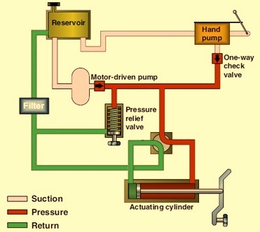
Fig 1 Basic hydraulic system
The hydraulic reservoir is a container for holding the fluid required to supply the system, including a reserve to cover any losses from minor leakage and evaporation. The reservoir is usually designed to provide space for fluid expansion, permit air entrained in the fluid to escape, and to help cool the fluid. Hydraulic reservoirs are either vented to the atmosphere or closed to the atmosphere and pressurized. Fluid flows from the reservoir to the pump, where it is forced through the system and eventually returned to the reservoir. The reservoir not only supplies the operating needs of the system, but it also replenishes fluid lost through leakage. Furthermore, the reservoir serves as an overflow basin for excess fluid forced out of the system by thermal expansion (the increase of fluid volume caused by temperature changes), the accumulators, and by piston and rod displacement. The reservoir also furnishes a place for the fluid to purge itself of air bubbles that may enter the system. Foreign matter picked up in the system may also be separated from the fluid in the reservoir or as it flows through line filters. Reservoirs are either pressurized or non-pressurized. Baffles and/or fins are incorporated in most reservoirs to keep the fluid within the reservoir from having random movement, such as vortexing (swirling) and surging. These conditions can cause fluid to foam and air to enter the pump along with the fluid.
For the purpose of the hydraulic components performing correctly, the fluid is to be kept as clean as possible. Contamination of hydraulic fluid is one of the common causes of hydraulic system troubles.
Foreign matter and tiny metal particles from normal wear of valves, pumps, and other components usually enter the hydraulic system. Strainers, filters, and magnetic plugs are used to remove foreign particles from a hydraulic fluid and are effective as safeguards against contamination. Magnetic plugs, located in a reservoir, are used to remove the iron or steel particles from the fluid. Strainer is the primary filtering system that removes large particles of foreign matter from the hydraulic fluid. Even though its screening action is not as good as a filter’s, a strainer offers less resistance to flow. Strainers are used to pump inlet lines where pressure drop must be kept to a minimum. Filter removes small foreign particles from a hydraulic fluid and is most effective as a safeguard against contaminants. Filters are located in a reservoir, a pressure line, a return line, or in any other location where necessary. They are classified as full flow or proportional flow. A bypass relief valve in a body allows a liquid to bypass the filter element and pass directly through an outlet port when the element becomes clogged. Filters that do not have a bypass relief valve have a contamination indicator. This indicator works on the principle of the difference in pressure of a fluid as it enters a filter and after it leaves an element.
Accumulators are like an electrical storage battery. A hydraulic accumulator stores potential power, in this case hydraulic fluid under pressure for future conversion into useful work. This work can include operating cylinders and fluid motors, maintaining the required system pressure in case of pump or power failure, and compensating for pressure loss due to leakage. Accumulators can be employed as fluid dispensers and fluid barriers and can provide a shock absorbing (cushioning) action. Accumulators can be spring loaded, bag type or piston type.
Hydraulic pumps convert mechanical energy from a prime mover (electric motor) into hydraulic (pressure) energy. The pressure energy is used then to operate an actuator. Pumps push on a hydraulic fluid and create flow. The combined pumping and driving motor unit is known as hydraulic pump. The hydraulic pump takes hydraulic fluid from the storage tank and delivers it to the rest of the hydraulic circuit. In general, the speed of pump is constant and the pump delivers an equal volume of fluid in each revolution. The amount and direction of fluid flow is controlled by some external mechanisms. In some cases, the hydraulic pump itself is operated by a servo controlled motor but it makes the system complex. The hydraulic pumps are characterized by its flow rate capacity, power consumption, drive speed, pressure delivered at the outlet and efficiency of the pump. The pumps are not 100 % efficient. The efficiency of a pump can be specified by two ways. One is the volumetric efficiency which is the ratio of actual volume of fluid delivered to the maximum theoretical volume possible. Second is power efficiency which is the ratio of output hydraulic power to the input mechanical / electrical power. The typical efficiency of pumps varies from 90 % to 98 %. The hydraulic pumps are generally of two types, namely (i) centrifugal pump, and (ii) reciprocating pump.
Hydraulic actuator receives pressure energy and converts it to mechanical force and motion. An actuator can be linear or rotary. A linear actuator gives force and motion outputs in a straight line. It is more commonly called a cylinder but is also referred to as a ram, reciprocating motor, or linear motor. A rotary actuator produces torque and rotating motion. It is more commonly called a hydraulic motor or motor.
The pressure regulation is the process of reduction of high source pressure to a lower working pressure suitable for the application. It is an attempt to maintain the outlet pressure within acceptable limits. The pressure regulation is performed by using pressure regulator. The primary function of a pressure regulator is to match the fluid flow with demand. At the same time, the regulator must maintain the outlet pressure within certain acceptable limits
Valves are used in hydraulic systems to control the operation of the actuators. Valves regulate pressure by creating special pressure conditions and by controlling how much fluid will flow in portions of a circuit and where it will go. The three categories of hydraulic valves are pressure control, flow (volume) control, and directional control. Some valves have multiple functions, placing them into more than one category. Valves are rated by their size, pressure capabilities, and pressure drop/flow.
The three common types of pipe lines in hydraulic systems are pipes, tubing, and flexible hoses, which are also referred to as rigid, semi-rigid, and flexible lines. The two types of tubing used for hydraulic lines are seamless and electric welded. Both are suitable for hydraulic systems. Knowing the flow, type of fluid, fluid velocity and system pressure help determining the type of tubing which need to be used. Hoses are used when flexibility is necessary.
Fittings are used to connect the units of a hydraulic system, including the individual sections of a circulatory system. Many different types of connectors are available for hydraulic systems. The types that are to be used depend on the type of circulatory system (pipe, tubing, or flexible hose), the fluid medium, and the maximum operating pressure of a system. Some of the most common types of connectors are threaded connectors, flared connectors, flexible hose couplings, and reusable fittings.
Hydraulic-circuit diagrams
Hydraulic-circuit diagrams are complete drawings of a hydraulic circuit. Included in the diagrams is a description, a sequence of operations, notes, and a components list. Accurate diagrams are essential to the designer, the people who build the machine, and the people who maintain the hydraulic system. There are four types of hydraulic-circuit diagrams. They are block, cutaway, pictorial, and graphical. These diagrams show (i) the components and how they will interact, (ii) how to connect the components and (iii) how the system works and what each component is doing.
Block diagram shows the components with lines between the blocks, which indicate connections and/or interactions. Cutaway diagram shows the internal construction of the components as well as the flow paths. Because the diagram uses colours, shades, or various patterns in the lines and passages, it can show the many different flow and pressure conditions. Pictorial diagram shows a circuit’s piping arrangement. The components are seen externally and are usually in a close reproduction of their actual shapes and sizes. Graphical diagram is the short-hand system of the industry and is usually preferred for design and troubleshooting. Simple geometric symbols represent the components and their controls and connections. A typical graphical diagram for a hydraulic circuit is shown in Fig 2.
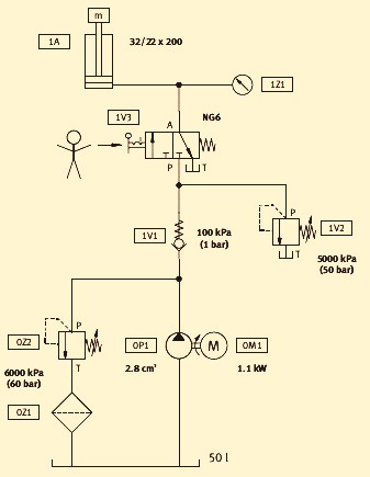
Fig 2 Typical graphical diagram for a hydraulic circuit

Leave a Comment