Types of Burners in Reheating Furnaces
Types of Burners in Reheating Furnaces
Presently steel industry is facing major challenges of the continuous reduction of the environmental emissions while improving the economic viability of the processes. Reheating furnaces due to their high-energy consumption is one area where attention of steel industry is needed. They are important equipment which contribute to the productivity and energy efficiency of the steel plant.
Modern reheating furnaces are walking beam furnaces where the beams lift the charge steel material (billets, blooms or slabs) inside the furnace and move it to the next position. The heating is done in these furnaces by direct firing of the fuel both from above and below of the steel charge material, using roof burners (to heat the roof which then radiates the heat to the steel charge material) and/or long flame burners (side walls or/and front wall). Common fuels used in the reheating furnaces are mixed gas of low calorific value (blast furnace gas mixed with the coke oven gas and the converter gas), coke oven gas, heavy oil, low sulphur heavy stock (LSHS), or natural gas.
The important parameters for a reheating furnace includes the combustion system consisting of the fuel used, supply and the technological condition of the combustion air, the burners and their location for proper heat distribution, preheating of combustion air and fuel gas, waste heat recovery system, air fuel ratio, control of furnace draft, the furnace exhaust system, and furnace parameters measurement and control system. The furnace combustion system besides supporting the required productivity level of the furnace, ensures efficient utilization of heat input, lower heat losses, efficient recovery of waste heat, minimal damage to the furnace refractories, and lower generation of green house gases specially NOx. The furnace combustion system also ensures a furnace atmosphere which minimizes scale formation on the steel surface.
Heat recovery systems have been widely used in steel plants in order to reduce the exhaust gas heat losses of reheating furnaces. As exhaust gas heat loss accounts for the high percentage of thermal loss, furnace efficiency is improved and fuel consumption is reduced by the use of heat recovery system. Two types of heat recovery systems are normally employed namely centralized system and distributed system. The centralized heat recovery system preheats combustion air with a metal recuperator by the heat of the exhaust gases and is currently in widespread use. However, the maximum preheated air temperature attainable by this method is around 600 deg C with a furnace temperature of around 1300 deg C due to material temperature limitations. The distributed heat recovery system consists of a switching type regenerative burner system with the use of ceramic (usually alumina) balls as the regenerative media. It provides higher temperature preheated air than that of the centralized system.
Burners used in the reheating furnaces constitute one of the important aspect which decides the energy efficiency of the reheating furnace. Different steel specifications require different temperature profiles in the reheating furnace. Hence for the proper heat distribution inside the furnace, it is important that the burners should have flexibility so that the operating personnel can adapt the combustion parameters to suit the diverse process conditions. Burners need to have proper turn down ratio, low NOx capabilities and high efficiency.
The arrangement of burners in a reheating furnace is also very important for heating characteristics of the furnace. According to the position of the burners in the furnace, arrangements are classified into three heating methods namely (i) Use of axial-flow burners in front wall, (ii) use of side burners in side walls, and (ii) Use of flat flame radiant burners in the roof. Each heating method has its own characteristics. A particular heating method or a combination of heating methods is adopted for a reheating furnace to suit the local conditions in the steel plant. In steel plants where multiple fuels are available, the burners should have capability of utilization of multiple fuels.
The reheating furnace is to be designed to ensure that within a given time the steel charge material is heated uniformly to a desired temperature with the minimum amount of fuel. Since the heating is carried out with the use of burners, the following is necessary to be ensured for proper heat distribution.
- Firing of the reheating furnace is to be done by burners located at the discharge end of the furnace and located at the top and/or bottom to the steel charge material.
- The flame must not touch or get obstructed by any solid object. Any obstruction causes the fuel particles to de-atomize, which affects combustion and causes black smoke. If the flame impinges on the steel charge material, then the scale losses increases. If the flame impinges on refractories, products from incomplete combustion can settle and react with the refractory constituents at high temperatures causing damage to the furnace refractories.
- The flames of different burners must be clear of each other, as intersecting flames cause incomplete combustion. It is also desirable to stagger burners on opposite sides.
- The burner flame has a tendency to travel freely in the combustion space just above the material. For this reason, the axis of the burner in the furnace is not to be placed parallel to the hearth but at an upward angle. However the flame must not hit the furnace roof.
- Large burners produce longer flames, which is usually difficult to be contained within the furnace walls. Hence a large number of burners of lesser capacity are generally employed to ensure a better heat distribution inside the furnace and also to increase the furnace life.
Burners used in the reheating furnaces are either long flame or flat flame.
Flat flame Burner
The flat flame burners (FFB) are usually used on the roof of the reheating furnace. Due to these burners indirectly oriented radiant heat transfer takes place. The heat from fuel combustion is transferred to the steel charge material not only directly from the flame, but also through the roof refractory lining of the furnace. The flame, which is normally non-luminous, is characterized by high temperature and relatively low emissivity corresponding to selective radiation of carbon dioxide and water vapour. For lack of flame impact on the steel charge material the FFB heated furnaces are known as indirect heating furnaces.
The burners are designed to spread the flame over the roof surface in a thin layer. As the flow rate of the combustion gases in the direction of the burner axis is negligible, the temperature of the refractory roof is increased on account of intensive heat transfer from the flame to the roof. In this way, the refractory roof acts as the chief radiating surface.
The use of flat flame burners is considered to be appropriate and advantageous when the steel charge material in the reheating furnace has a large flat surface, possibly parallel to the furnace roof and when the heating temperature of the steel charge material is above 900 deg C. The following are the main advantages and disadvantages of the FFB fired furnaces
The temperature distribution in the FFB furnace chamber and in the steel charge material is more uniform. There is satisfactory temperature control of the individual zones enabling to achieve the necessary furnace output.
- The faster heating rates, due to FFB, diminish the time of steel charge material exposure to high temperature. Hence the occurrence of surface oxidation or the phenomena like decarburization and coarse grain steel structure is greatly reduced.
- A major reduction in fuel consumption of up to almost 40 % can be achieved following a 100 % to 50 % decrease in furnace output.
- Intensive mixing of gaseous fuel and combustion air ensures fast and complete combustion of the mixture at low excess air value.
- A basic disadvantage of roof heating is the risk of overheating the steel charge material surface following a sudden change in furnace output.
- An excessive heating rate at the beginning of the furnace chamber may induce unwanted thermal stresses and structural deformations in the steel charge material.
Long flame burners
A large variety of long flame burners of various characteristics and different capacities are available in the market. These burners are available in various capacities and to suit use of different fuels such as oil, gas or multiple fuels.
In the reheating furnace with the long flame burners, since the major part of the heating of the steel charge material takes place by convection, the re-circulation of products of combustion substantially contributes to the speed of heating and temperature uniformity. Long flame burners produces high velocity gases which entrain and recirculate the combustion gases to achieve temperature uniformity in the furnace with minimum of excess air.
The burners at the front wall of the reheating furnace are usually of longer flame while those at the side wall of the furnace are of shorter variable flame. The burners at the front wall of the reheating furnace are normally of axial flow burning type and need wide range of adjustment. They are large capacity burners and have limitation of the length per zone in the direction of the furnace length. The flow of burning gases inside the furnace is smooth along the furnace length. The nose parts of the burners makes the structure of the furnace complicated. With these burners there is uniformity of heating along the furnace width but the temperature tend to fall at the nose parts in the direction of furnace length. The workability is relatively good except around burners at lower area where the temperature is relatively high.
The burners at the side wall needs narrow range of adjustments. These burners are also of large capacity and have limitation in the direction of furnace width. The flow of burning gases tends to drift since the direction of the burners is at right angle with the direction of the furnace length. Since there is no nose part in these burners, they do not complicate the furnace structure. The burners have good uniformity in the direction of furnace length but poor uniformity in the direction of furnace width. The workability is relatively good with these burners.
Regenerative and recuperative burners
A regenerative burner is with a heat recovery system that recovers the waste heat of the furnace exhaust gas to heat up the combustion air needed for the burning of the fuel at the burner. Use of regenerative burners for reheating furnaces can provide significant energy savings.
The regenerative burners are designed to recover the heat to the inlet air by transferring the heat from the exhaust gas to the inlet air which is to be used in the combustion. The regenerative burner has two set of burners each with a regenerator and the reversing valve. The regenerator uses the ceramic (usually alumina) balls to collect the heat. While the first regenerative burner is firing, the other is exhausting the furnace gases. The exhaust gas is passed through the regenerative burner body and transfers the heat to the ceramic balls. Hence, the heat from exhaust gas is transferred to the inlet air since it is passed through the heated ceramic balls.. The reversing valve sets the direction of the air flow that enters into the burner head, which makes the inlet air temperature similar to the operating temperature. Due to a high preheat combustion air temperature, the regenerative burner can save the fuel and make the combustion with high efficiency.
In case of a recuperative burner, the structure of the burner is the similar to the radiation heat exchanger tube which heats the inlet air up to the higher temperature (about 750 deg C) by recovering the heat from the exhaust gas to the inlet air. Hence, the exchanged heat in the burner can improve the combustion efficiency and save the fuel cost approximately 25 % to 30 %.
The regenerative burner principle is shown in Fig 1. The first burner is in the firing mode while the second burner is in the exhausting mode. The first burner is firing with the warm combustion air blowing across its burner. The second burner is receiving the hot exhaust gas out from the furnace to its ceramic balls in order to keep the heat in the burner. Only after passing its heat, the exhaust gas gets released. After a period of half a minute to one minute, the second burners is switched to fire mode while the first burner starts receiving the hot exhaust gas. The firing and receiving mode of burner operates alternatively and continuously until the reheating furnace is stopped. The high preheated air temperature makes the combustion process very efficient.
The recuperative burner principle is also shown in Fig 1. The temperature of the inlet air is preheated before the combustion in the furnace by the heat exchange technique. The exhaust gas flows through the burner equipped with a heat exchanger installed inside the burner. The heat from the exhaust gas is exchanged to the inlet air before it flows out from the burner. The exhaust gas runs through the area around the outside of the burner and the heat is exchanged inside the burner.
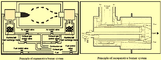
Fig 1 Principles of regenerative and recuperative burners systems
Oxy fuel burners
Oxy fuel refers to the practice of totally replacing air as the source of oxidizer for combustion with industrial grade oxygen. Oxy fuel combustion reduces or eliminates nitrogen in combustion air and substantially reduces waste heat carried out with flue gas. The oxy fuel burners can be used in high temperature reheating furnaces where temperature uniformity is critical and extremely low NOx emissions are desired.
The general advantage of replacing air with industrial grade oxygen is that the nitrogen content present in the air brought to the combustion process gets almost or completely eliminated. Reduction of nitrogen in combustion allows for higher flame temperature and combustion efficiency as lower combustion gas volume reduces the amount of heat taken from the flame and lost in the exhaust gases.
The benefits of using oxy fuel as compared to air fuel combustion are namely (i) reduced energy consumption, (ii) increased heating rate resulting in higher production with no increase in furnace temperature set point, and (iii) reduced furnace emissions
Oxy fuel flames have a higher temperature with less volume and length than air fuel flames. The flame characteristic with oxy fuel needs to be considered when designing oxy fuel burner systems for steel reheat applications. Generally, steel heating demands even temperature distribution so that localized over heating or under heating in the product is avoided. The type and placement of oxy fuel burners depends on the type of furnace and the proximity of flames to steel product.
Oxy fuel flames have a higher temperature with less volume and length than air fuel flames. The flame characteristic with oxy fuel needs to be considered when designing oxy fuel burner systems for steel reheat applications. Generally, steel heating demands even temperature distribution so that localized over heating or under heating in the product is avoided. The type and placement of oxy fuel burners depends on the type of furnace and the proximity of flames to steel product.

Comments on Post (1)
Aditya
How to reduce bentonite specific consumption.