Rolling of steel in Hot Strip Mill
Rolling of steel in Hot Strip Mill
Hot strip mills in these days are either conventional hot strip mills or strip mills for rolling thin slabs. The primary function of the conventional hot strip mill (HSM) is to reheat the semi-finished steel slabs (rolled or continuously cast) to the rolling temperatures and then to roll them thinner and longer through a series of rolling mill stands driven by large motors and finally coiling up the lengthened steel sheet for its easy handling and transport. Coils are produced with an inside diameter of 750 mm on the coilers, with an outside diameter of up to 2400 mm and with the limitations of coil weight up to 220 kg per cm width. The hot strip mill supplies coils for cold rolling mill, strip shearing and slitting units as well as a finished product for shipment directly to the customers. Most material is transported out of the mill area by an automated coil handling system to the storage aisle.
Attributes imparted to the strip by the hot rolled strip mill include surface quality, thickness, width, and flatness control as well as strip profile.
Rolling of steel slabs in hot strip mill consists of several sub-processes and at the end of them the final product ‘hot rolled coil’ is produced. The main sub-processes are (i) heating of steel slabs in the reheating furnace, (ii) descaling of the heated slab and its sizing in sizing press, (iii) rolling in the roughing mill and secondary descaling, (iv) rolling in the finishing mill, (v) control cooling of the hot rolled strip and (vi) coiling of the rolled strip.
Reheating of the slab
Critical to the hot strip mill is the reheating furnace. Modern hot strip mills are equipped with state of the art walking beam reheating furnaces which have replaced and outperformed older pusher type reheating furnaces. These reheating furnaces are nominally rated to produce heated slabs in the range of 250 tons per hour to 300 tons per hour with a capability of producing up to 25 % extra to their rated output with some sacrifice in slab temperature uniformity. The furnace needs around 350,000 kcal of fuel gas per ton of slab for the heating of the slab from room temperature to a temperature range of 1100 deg C to 1250 deg C. The inspected slabs as per rolling schedule are placed one at a time on the furnace charging roller table in the slab yard and positioned in front of the charge door on the reheating furnace. When space is available in the furnace, the pusher arms push the slab into the furnace. Once inside, the slabs are supported around 2.5 m above the furnace floor by water-cooled, refractory-coated pipes called ‘skids’. To minimize the cold spots (‘skid marks’) left in the slabs, the skid spacing changes in some design of the reheating furnaces around two-thirds of the way through the furnace. Two independent sets of skids, one fixed and one walking, take turns supporting the slab as it is walked through the furnace by a massive sub-frame energized by a pair of large hydraulic cylinders. Depending on the furnace design, the interior of the furnace is divided into several (five to ten) zones for temperature control. The preheat and heating zones combust a mixture of fuel gas and preheated combustion air with the burners on the roof and on the side walls of the furnace, both above and below the skids, to heat the slab nearly to its discharge temperature.
Most of the preheating of the steel slab is achieved by the hot exhaust gases rushing past the slabs on the way to the recuperators. Whatever heat is left in the exhaust gases preheats the incoming combustion air to around 500 deg C to 550 deg C in the recuperators. In the heating zone the steel is primarily heated by radiation by the hot furnace walls. In the soak zone, the burner sizes and locations are such so as to maintain a uniform temperature within the zones to equilibrate any cold spots in the slabs.
Refractory dividers help to physically distinguish the zones, and thermocouple temperature sensors throughout the furnace interact with the automatic burner control systems to maintain the target temperatures in each zone. Complex computer models calculate the targeted roughing mill exit temperature to obtain a furnace discharge aim temperature. Estimating the temperature profile through the thickness of each slab in the furnace on an ongoing basis, the computer aids the operator in selecting the production rate and zone set-points that maximize production of steel slabs uniformly heated to as close to the target temperature as possible. After the rolling process begins, as the steel exits the roughing mill, its temperature is fed back to the furnace, updating the computer models and informing the furnace operator as to the temperature uniformity.
When the slab reaches the ‘discharge door’ at the exit end of the furnace, and the computer has determined that the slab has been sufficiently heated, the door opens and the arms of the extractor reach beneath the slab, lift it off of the skid supports, and draw it out of the furnace. The reheating furnace has usually two extractors. These extractors can act independently of one another to remove double-charged slabs one at a time or in combination to extract the longer slabs. The hot slab is placed on the entry roller table which carries it into the roughing mill through a scale breaker.
Descaling and sizing of slab
Descaling of heated slab is a must in the hot strip mill for attaining good surface quality of the hot rolled strip. Descaler operation need to be optimize in order to ensure maximum scale removal and hence enhanced cleaning at minimum cooling of the heated slab.
After leaving the reheating furnace, the slab passes at a speed ranging from 0.15 m/sec to 2.0 m/sec through a descaling unit, an enclosure employing two pairs of spray headers. These spray headers are of simple, maintenance friendly design and spray high pressurized water (pressure of water up to 400 kg/sq cm) on the slab to remove the oxidized iron layer that forms at the surface of the slab in the oxygen rich atmosphere of the reheating furnace. These headers are usually equipped with advanced nozzles to spray water effectively. The descaler is normally of closed design to prevent water from escaping and there is optimized water flow inside the descaler. The water consumption for descaling ranges from 200 cum/hr to 700 cum/hr.
Modern hot strip mills are equipped with a sizing press in place of an edger. The essential technological advantage of the sizing press is that besides resulting into large width reduction (up to 350 mm) in one pass, it causes distinctly better through forming of the slab right through its centre. The slab sizing press produces flatter ‘dogbones’ leading to reduced spreading and greater sizing efficiency. The sizing press offers distinct advantage of far more flexibility in the hot strip production. The width reduction in the sizing press pass enables the number of sizes in the continuous casting to be standardized to a few widths which in turn helps in the enhancement of the productivity in continuous casting machine. A special short stroke mode at the slab head and tail ends results into less cropping losses and higher yield.
Roughing mill and secondary descaling
In the semi continuous hot strip mill, the roughing mill consists of usually one or two roughing stands in which the slab is hot rolled reversibly. The slab is rolled in roughing mill 5 or 7 times repeatedly to reach the minimum thickness requirement of around 30 mm. The roughing mill also contains edger rolls which are used to roll the edge of slab and center it.
The hot strip mill can be either a high performance mill or a compact mill. The difference in the two mill types is the coil box which, in compact hot mills, is installed between the roughing and the finishing mill. It equalizes the transfer bar temperatures to the effect that with as few as six finishing stands final gauges of 1.2 mm can be achieved. The thickness of transfer bar which the coil box can handle usually ranges from 20 mm to 40 mm and the coiling speed is around 5.5 m/sec. The output capacity of a compact hot mill is normally in the range of 3.5 million tons per annum, while the high-performance mills can achieve up to approx. 5.5 million tons per annum.
High throughput for the HSM asks for a minimum number of passes in the roughing mill which is of particular importance for semi continuous HSM. This means high reduction per pass, which is only possible with excellent roll biting behaviour. It is well-known that roll bite is improved with lower carbide content and lower hardness of the working surface of the work rolls.
In a continuous HSM, the roughing mill is usually made up of six independent rolling mill stands, the last four to five of which incorporate small vertical rolling mills called edgers. Heated slabs are rolled through one stand at a time to produce so-called transfer bars suitable for finish rolling. High-pressure water-jet nozzles clean the oxidized iron, or scale, from the surface along the way. As the transfer bar exits the last roughing mill stand, the thickness of the leading edge of the bar is estimated. Similarly, a pyrometer measures the temperature profile of the bar from head to tail and a special camera photographs both ends. Depending on the gauge, width, and grade of the product to be rolled, the average temperature of the bar as it exits the last roughing mill normally ranges from 1050 deg C to 1150 deg C. This data is collected in anticipation of finish rolling.
The last four to five roughing mills each incorporate edgers for width control. The individual roughing mills are spaced increasingly further apart to accommodate the lengthening of the transfer bars as they are rolled thinner and thinner. At the very high temperatures at which the steel is rolled in the roughing mill, it is very plastic and ‘flows’ easily. Consequently, as the slab is reduced, bar tends to spread width-wise at its extremities. The edgers serve to hold a uniform width through the bar’s length.
The roughing mill requirements with respect to work roll properties for roughing stands are summarized as follows.
- High roll bite based on high friction coefficient, allowing high reductions per pass without chattering or slippage and consequently higher throughput with reduced heat loss of the product.
- High resistance of shell material against wear, thermal fatigue and oxidation/corrosion, resulting in low and homogeneous wear allowing longer rolling campaigns and reduced downtime.
- High heat and fire crack resistance which stands for a smooth tiny fire crazing network preventing high damage caused by mill stalls.
- Perfect roll surface quality over long runs, which is related to no peeling, no banding, no micro-spalling during one campaign time.
- High safety against roll failures generated by any kind of operation conditions including mill incidents, high thermal and mechanical loads etc.
Because a square head-end is critical to properly threading the finish mills and the down coilers, and because an uneven tail can bruise work-roll surfaces or cause threading problems for the next production process, the head- and tail-ends of nearly every transfer bar are cropped by a pair of large steel drums each with a shear blade extending along its length. With the bar crawling along the roller table at around 30 m/min, sensors detect its position and speed in order to time the crop shear drums to optimize the amount cropped; since transfer bars are around 30 mm thick, each extra cropping means quite a good expensive cropping losses.
Between the crop shear and the first rolling stand of the finishing mill there is normally second scale breaker, whose task is the final scale removal. Water sprays above and below the transfer bar at around 200 kg/sq cm pressure break up the scale that has re-formed (secondary scale), as well as any scale that has persisted through earlier descaling operations. Level adjustment of the top spraying headers and water collecting troughs enables optimum adaption of the transfer bar being handled. Due to the special nozzle arrangement, different degrees of cooling on the transfer bar upper-side underside are minimized.
After secondary descaling, the bar is pinched by a pair of pneumatically-actuated rolls to mechanically loosen any remaining scale, which, as the processing temperatures cool off, becomes increasingly sticky even as it returns ever more slowly to the surfaces of the still red-hot steel.
Finishing mill
The finishing mill of HSM usually has five to seven finishing roll stands, which reduce the thickness of the transfer bar down to the gauge required. The rolling speed is set to allow the last stand to perform the final reduction at the finishing temperature, between 820 deg C to 900 deg C, so as to achieve certain mechanical properties in the hot rolled strip. The finishing mills roll the transfer bar in tandem, meaning each bar is rolled through all the finishing stands at once. The hot steel is quite fragile as it is rolled and tension between the finishing mill stands must be closely controlled at very low levels in order to avoid stretching or tearing the strip.
Adjustments are made as necessary to ensure the strip threads properly through each of the mills without looping up and folding over or stretching and tearing apart. The position of each roll is fed back to the finishing mill’s sophisticated automation system which, along with information from the load cells that monitor rolling force and from the X-ray gauge measuring final strip thickness, work to smoothly adjust the roll gaps and speeds to maintain stable rolling of strip to the necessary thickness in spite of the temperature variations present in every bar.
Once the bar is threaded between each successive pair of mills, a looper engages the strip to monitor the tension between the stands. The loopers arranged between the finishing stands of the HSM safeguard correct mass flow control and hence contribute to the stable rolling of finished strip down to the final thickness of the strip. The loopers are driven by hydraulic cylinders.
For the rolling of the ultrathin strip, loopers featuring differential tension measurement are used to detect strip tension differences between the drive and the operator sides which can be eliminated by swiveling the top roll set. Minor tension differences contribute to reliable unthreading and help prevent tail end crashes.
The function of the tensiometer looper is to measure the distribution of the tensile stresses across the width of the strip which represents an essential prerequisite for automatic online flatness control. A tensiometer is preferably arranged between the last two stands.
The inter-stand facilities are vitally important for the production of hot rolled strip with top surface quality. Important equipment includes (i) entry and exit guides, (ii) work roll cooling system, (iii) anti peeling device, (iv) roll gap lubrication system, and (v) inter-stand cooling and descaling systems. Close interplay of all these facilities is a must to achieve an optimal result. Sideguard featuring hydraulic width adjustment ensure exact positioning within minimum time. The strip guide areas are designed so that all wearing parts can be replaced quickly. The cooling efficiency is improved by optimized selection and arrangement of nozzles.
The combination of roll gap cooling, roll gap lubrication and improved exit side cooling systems reduces the roll temperature. This results in a thinner oxide layer on the roll surface with less work roll peeling for consequence. Lubrication inside the roll gap minimizes friction, thereby enabling rolling force reduction of 20 % to 30 %. In this way it is possible to redistribute the rolling force for optimizing the pass schedule and thinner final strip gauges. Added to this that chattering or vibrations in the stand are prevented which leads to longer roll service lives.
A profound metallurgical transformation in the crystal structure takes place as the material cools, which, depending on the specific chemistry of the material, typically is between 800 deg C and 850 deg C. Additionally, the mechanical properties of the final product respond to some degree to the specific temperature at which the final reducing pass is taken.
Consequently, a finishing temperature for each product is specified and mill automation adjusts the speed of the first finishing mill stand based on its temperature and the extent to which the bar is expected to cool as it makes its way through each stand, in order to allow the strip exiting the finishing stands to meet the target temperature. The last hot working operation is usually conducted above the upper critical temperature of 787.8 deg C which permits the rolled steel to pass through a phase transformation after all the hot work is finished. This produces a uniformly fine, equiaxed grain throughout all of the steel. If part of the hot rolling is conducted on steel that has already partially transformed to ferrite, the deformed ferrite grains will coarsen during the self-anneal that occurs during the cooling of the coiled steel. This condition could limit the suitability of the steel for some severe drawing applications.
Since each transfer bar spends approximately one minute in the finish mill, from head to tail, the temperature of the steel going into the finishing stands is significantly lower, perhaps 100 deg C, by the time the tail-end is rolled as compared to the head-end. Consequently, once the first 150 m of the strip has been rolled at the thread speed and a down coiler has been threaded, the mill begins to accelerate at a ‘zoom’ rate that had been calculated from the temperature profile of the bar as it exited the last roughing mill. Top speeds as high as 20 m/sec are reached by the mill automation seeking to maintain the specified finishing temperature throughout the final product. A pyrometer placed after the last stand updates the finishing mill’s computer models and allows for the addition of this temperature to strip quality records.
With the tremendous rolling forces present in a rolling mill, it is not sufficient to simply set the gap between the work rolls to the thickness desired and expect the strip to come out the other side at that thickness. With rolling forces regularly exceeding 3,000 tons in the early finishing stands, the mill housings can be expected to stretch as much as 10 to 15 mm after the bar enters the bite when rolling wide, stiff, and/or light-gauge products. When setting the roll gaps for threading, it is critical that this factor be compensated for in each of the mill stands; to do so, sophisticated models are used by mill automation to estimate the rolling force for each transfer bar in each stand based on, among other things, the incoming and outgoing thickness, width, steel grade, and estimated instantaneous temperature. The models employed by the mill automation are updated with the rolling parameters and product measurements each time a new slab is rolled, continually optimized the mills’ automation set-ups. Product quality and production yield benefit from scheduling products with similar gauge and grade to roll in succession, allowing automation to deploy the most recently utilized rolling model.
In addition to the degree to which mill stands stretch under rolling loads, the rolls deflect, or bend, under load since they are being forced apart in the middle by the strip but are supported at the ends by the bearings. This deflection is the source of the strip attribute commonly referred to as crown. Strip crown is initiated in the roughing mills and continues through each successive rolling mill stand. Strip crown is measured at the exit end of the finishing mills by a second, scanning X-ray gauge which traverses back and forth across the width of the strip as the steel is rolled. The thickness it measures is compared to the thickness measured by the primary X-ray monitoring the center-line gauge through the length of the strip and the difference is then plotted as a product quality record. Typically, the HSM produces material with between 0.025 mm and 0.075 mm of crown depending on a number of factors that include the gauge, width and grade of the finished product.
Operators of any roll stand have a degree of control over the shape of the roll gap by adjusting the screw-downs to increase or decrease the roll force present in that stand, influencing the degree to which the rolls deflect. The last four finishing mill stands generally incorporate hydraulic work-roll bending to give the operators additional control over the shape of the loaded roll gap. Operators adjust work-roll bending in these stands to influence the crown in the final product. The work-roll bending in the final finishing stand is used exclusively to create a roll gap shape that matches the profile of the strip exiting the prior finishing mill to produce a flat, final product.
The technologies incorporated in a modern hot strip mill to in improve the product quality are (i) automatic gauge control, (ii) automatic width control, (iii) work roll bending, (iv) continuous varying crown (CVC) , (and v) roll eccentricity compensation. CVC is a way to change the strip profile by using rolls with a profile. The gap between the rolls can be changed by axial shifting of the rolls. The CVC technique is also known as roll shifting technique. CVC technique has slower dynamics but a wider range than work roll bending. Since CVC and work roll bending complement each other, both the techniques are normally used in the modern hot strip mills.
During recent years, there is an increasing demand on the profile, thickness, flatness and the surface of the hot strip. For meeting this demand, the CVC technology has been upgraded. The improvements are both in the mechanical equipment and the process model.
Control cooling
After exiting the finishing mills, the strip is carried down by a large number of individually-driven rolls through four to 12 banks of low-pressure, high-volume water sprays that cool the red-hot strip to a specified coiling temperature between 400 deg C and 900 deg C and into down coilers. Side guides on either side of the run out table seek to keep the strip’s head-end pointed at the coilers; the final section of guides in front of each coiler adjusts to match strip width and features a pneumatic quick-close system that allows the operator to center the strip head-end as coiling begins.
Metallurgically critical to the properties of hot-rolled steel is the coiling temperature, as the coil cools from this temperature to ambient over the course of three days. Essentially a heat treatment comparable to annealing, the stresses imparted to the steel during reduction from the slab thickness down to the gauge of the hot strip are given the opportunity as the coil cools to relieve them. Though the steel is continually recrystallizing during hot rolling, reductions in thickness sometimes in excess of 99 % and taking place in less than ten minutes stress the steel considerably; coiling temperature is specified by product metallurgists to harness and manipulate those stress levels in search of optimal mechanical properties. The cooling of the hot rolled strip after its rolling in the last finishing stand is shown in Fig 1.
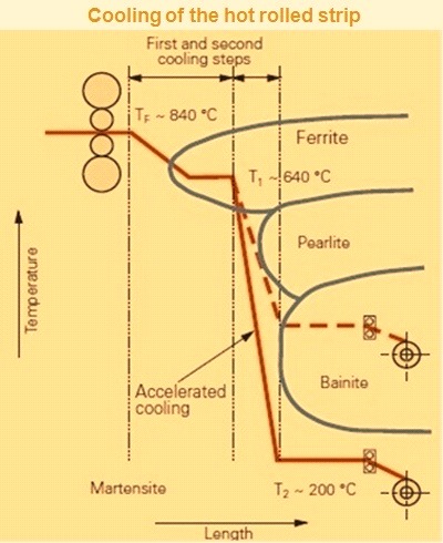
Fig 1 Cooling of the hot rolled strip
The exit area located between the finishing mill and the coiler of the hot strip mill is needed for the material transport and material temperature setting, and hence for attaining the mechanical properties. Selection of the roller spacings as a function of the strip thickness range safeguards reliable transport especially of the strip head.
In coaction with a highly efficient cooling model, the laminar cooling system arranged in this area ensures the desired coiling temperature as well as cooling so as to achieve the desired mechanical properties of the rolled stock.
The combination of laminar cooling system and edge masking system prevents excess cooling of the strip edges, thereby minimizing stress differences across the strip width. As a result, cold strip flatness is improved.
Product sold as hot rolled and hot rolled pickled and oiled to be laser cut by a customer is coiled at relatively high temperatures to try to relax the steel as much as possible so that parts cut from the coil lie flat even after residual stresses have resolved themselves around the part’s configuration. Conversely, coiling at a relatively cold temperature allows physical quality steel grades to retain higher internal stress levels and limits the size of the individual crystals and of the carbides that form within and between the crystals; each of these factors contributes to higher strength levels in the finished hot-rolled strip.
Cooling steel 200 deg C as it rushes past at speeds up to 20 m/sec requires tremendous amounts of water, so a large number of 152 spray headers, individually valved and controlled by the automation system, drench the steel from the top and bottom with curtains of water. The computer estimates, based on the thread speed of the strip and target finishing temperature, how much water is needed to cool the head-end, and the accuracy of this estimate is confirmed by a pyrometer in front of the down coilers. As adjustment to the number of sprays in use is needed, the computer turn sprays on and off to meet the targeted temperature through the length of the coil. Since the finishing mills accelerate once the down coiler is threaded to continue to make finishing temperature, increasingly more sprays are activated as the steel is rolled in order to compensate for the reduced time it spends on the run-out table.
Up to 300 cubic meters of water are pumped each minute throughout the HSM to cool finish-rolled strip, furnace skids, mill rolls, and coiler components, and to descale transfer bars. All water is recycled through a system of scale/sludge collection pits, through the laminar cooling system, and back to one of the two dedicated cooling towers.
Coiling
The coiling operation begins with a pair of pinch rolls that catch the strip head-end and establish tension across the run-out table and back to the finishing mills. The head-end is deflected by a gate down to the mandrel associated with the coiler and is guided around the mandrel by pneumatically-actuated wrapper rolls linked by aprons.
A hydraulic adjustable entry guide provided at the terminal end of the run out table serves to centre the strip before it enters the coiler station. The strip running at the finish rolling speed is reliably seized by the pinch roll unit and directed onto the coiler mandrel. A hold down roll on the entry side of the pinch roll unit prevents the strip (especially the heavy gauge strip) from bulging ahead of the pinch roll.
Once the head-end is all the way around the mandrel, laps begin to build around the mandrel, forcing away the wrapper rolls. Once the head-end is firmly gripped and friction and tension prevent the wraps of steel from slipping relative to the mandrel, the wrapper rolls disengage from the growing coil of steel. After the strip tails out of the finishing mill, the pinch rolls continue to hold back-tension to prevent the coil from unraveling; before the strip tail is pulled through the pinch rolls, the wrapper rolls are reengaged. A hydraulic coil car moves into place beneath the coil, and, after rising up to support the coil’s bulk, strips the coil from the mandrel and places it in position for transport to the automatic binding and labeling machine.
With a view to the wide size range of the hot rolled strip thicknesses from 1.5 mm to 20 mm, width from 750 mm to 2200 mm as well as the conditions and costs for maintenance of the coiler station, a three roll or a four roll coiler offers a large number of practical benefits.

Leave a Comment