Remedial measures and Campaign Life of a Blast Furnace
Remedial measures and Campaign Life of a Blast Furnace
The cost of rebuilding or relining a blast furnace (BF) is very high. Hence techniques to extend BF campaign lives are important and need to be pursued very actively.
Large BFs usually have a slightly higher campaign output per unit volume. This difference is because larger BFs generally are of more modern design and are well automated. Since the viability of an integrated steel plant depends on a continuous supply of hot metal (HM), which, in a plant with a small number of large BFs, puts great importance on long campaign life.
The techniques for prolongation of BF campaign life falls under the following three categories.
- Operational practices – The control of the BF process has a major effect on the campaign life. BF is to be operated not only for meeting the production needs but also to maximize its life. Hence it is necessary to modify operating practices as the campaign progresses and in response to the problem areas for the maximization of campaign life.
- Remedial measures – Once wear or damage that affects the life of the BF becomes evident, engineering repair techniques are to be used or developed to maximize campaign life.
- Improved designs – As improved materials and equipment are developed, these are to be incorporated into future rebuilds to extend the life of critical areas of the BF, where it is cost effective to do so.
Remedial measures for improving the campaign life of the BF are discussed in this article. The measures which are normally adopted for improving the campaign life of BF are described below.
Cold repairs and gunniting repair
The stack refractory brick work is usually exposed to mechanical wear in the upper part and also to thermal and chemical wear in the lower part of the BF. For ensuring a stable operation of the BF throughout its campaign life, it is necessary that the stack lining profile of the BF is kept in a balanced condition in the circumferential direction.
Intermediate relining (rebricking) of the stack area is done after the BF is blown down. This is time consuming but give an extension to BF campaign life which is normally more than 5 years with normal operating practices.
The stack and the bosh area can be gunnited with alumina based castables by adopting cold gunniting practice which means the cooling the BF completely and constructing of the scaffolding from where the gunniting operators can carry out the gunniting work. However this process is time consuming. In order to decrease the stoppage time, remote control gunniting system has been developed.
With the help of the remote controlled gunniting system, repairs with alumina based castables can be made to both the stack and bosh areas using closed circuit television to monitor the work. This system eliminates the need for work men to enter a hot furnace. The total shut down needed for the application of the castables to the bosh and stack areas of the BF by using this remote controlled gunniting technique is only a few days. The number of days depends on the size of the furnace, extent of gunniting needed, and the amount of preparatory work carried out.
The remote controlled gunniting device is suspended from a cantilever beam by cables and inserted through a door in the side of the stack near the BF top. It is then positioned in the centre of the BF using a gantry. The gunniting operator uses a continuous feed refractory gun to apply a mixture of monolithic material and water to the wall of the BF at a uniform distance and from a constant 90 deg angle. The gunniting mechanism can be rotated 360 deg and can be raised and lowered to allow the operator to reach all parts of the stack. As each revolution is completed, the gunniting device is simply raised to the next level. The operator can stop the rotation to gunite more in the seriously eroded areas. The unit is normally equipped with lights to improve the visibility of the operator.
The advantage of this technique is that the re-profiling of the BF can be completed within a few days of outage against a large number of days needed for cold gunniting. Since the equipment is operated by remote control from a platform which is situated outside the BF, there is no need to wait for the BF to cool before the gunniting repairs to begin.
Before the gunniting operation, cleaning of the stack and the removal of large scabs is an important prerequisite. The removal of loose refractory materials and/or accretions can be done by water jetting and cleaning of the stack can take in around 10 to 15 hours. During gunniting, rebound of the material is to be controlled. Rebound material is to be melted after the furnace starts. To melt a high rebound material can bring several problems to the BF operator.
When the gunniting procedure is completed, the BF is normally dried by controlled blowing of low temperature hot blast through the BF. The top gas temperature is progressively raised to around 400 deg C by increasing the hot blast temperature. The target is to raise the temperature at 150 mm back of the applied material to 120 deg C to drive off the moisture coming from the gunniting operation. If this is not done then during the rapid heating after the BF has started, there can be massive spalling.
The length of a shutdown for this robot gunniting depends on the BF size and the extent of gunniting needed and normally it is in the range 4 to 8 days. The life of the gunnited refractories varies and depends on several factors. For a BF which runs at high productivity levels after gunniting repairs and without frequent outages, expected life of the gunnited refractories can be in the range of 9 to 15 months.
The life of gunnited repairs can be extended by the addition of attachments to the furnace shell. In the hex-frame gunniting method, a steel frame with hexagonal grates is fixed to the shell, where the brick lining is badly worn, and a castable refractory is gunnited onto the frame to a thickness of 150 to 200 mm to rebuild the lining. The advantage of this method is that the castable can be fully gunnited up to the back side of the grates and that the gunnited castable has high strength. The hex-frame gunniting method is expected to extend the life of the upper stack lining under low thermal loads. The installation of cooling pipes in the upper stack can also give additional support to gunnited refractory.
Enhanced cooling
Enhanced cooling in critical areas of the BF wall areas is one way to promote prolongation of the BF campaign life. One critical area is the tap hole in a blast furnace. In some BFs, a refrigeration unit (a chiller) is being used to cool the water being pumped to the staves directly below the tap hole (the area with the most carbon wear). Stave water temperature is reduced to around 5 deg C compared with the normal 30 to 35 deg C without the use of chilled water. This chilled water helps a faster build up and thicker skull in this area. As a result, the thickness of the solidification layer in the hearth gets increased and the carbon brick temperature is decreased accordingly.
An under hearth cooling system is sometimes used in case there is a trend of increasing temperature in the hearth bottom. Under hearth cooling pipes at a desired spacing of 500 mm are installed at the BF on planned stoppages. Recirculating water is passed through these pipes to extract heat. This helps in the sharp fall of the local temperature. A chiller system to cool the temperature of the recirculating water is also sometimes used to make the heat extraction more effective.
For further improvement in the durability of the upper stack lining, a method in which water cooled iron castings are installed has been developed. Water cooled iron castings are installed in such a manner that they are exposed in the BF, and a castable refractory is grouted into the gap between the worn brick lining and the water cooled iron castings. The water cooled iron castings can more adequately withstand thermal load variations than refractories. Water cooled iron castings are installed in some BFs in the upper shaft area of the BF for campaign prolongation.
Cylindrical cooling elements (known as cigar coolers) are also used as a water cooled refractory anchor or stave insert during the remedial repairs of the BFs for the prolongation of the campaign life. Cigar coolers also provide cost effective alternatives for extending the life time of new refractory linings, whether installed during relines, repairs or in new furnaces. Apart from the installation of such coolers in a newly relined BF and as refractory anchors, their mounting plate configurations include built in grout injection ports to save installation costs and time. In addition, special twin cylindrical coolers can be mounted on a common flange or plate containing such a built-in grouting port. This twin unit can then be installed in any location on the furnace stack that requires grouting, without the need to drill holes in the stack and weld grout nozzles in place. Cylindrical coolers can also be utilized to re-establish cooling in failed staves. The coolers are inserted through the shell into openings which are provided in the stave. These openings can be lanced or high pressure water cutting employed. The location pattern and size of the coolers is dependent upon the actual stave configuration and the location of the cast-in pipes, mounting bolts and piping connections.
Grouting and welding of BF shell
Grouting of BF shell is a well known technology to promote a long campaign life. Grouting of BF hearth, i.e. the injection of plastic refractory material through the shell from the exterior, is carried out (i) to backfill following repairs, (ii) to counteract gas leakage in the tap hole area, (iii) in the ‘brittle zones’ of the hearth wall, and (iv) in case of temperature rise in the hearth wall.
When carrying out grouting in the region of the hearth, tuyeres and elbow tops are to be closed. Since the grouting material flows well, it is sufficient to set the pressure for injection to 5 kg/sq cm. This prevents any brick residues due to build up of grout pressure from being pushed into the BF. The BF shell is to be cooled to prevent excessively rapid vaporization of plasticizers and consequent crack formation. Water free masses are normally used.
Blowing out of gas from the tap hole is caused by insufficient burning of mass because of the high thermal conductivity of SiC bricks used in that area and by deterioration of mortar used between brick and shell. For preventing blowing out of the gas, improvement counter measures are being practiced. These counter measures are given below.
- Injection of tar and resin through the BF shell around the tap hole for plugging of the gas passage.
- Ramming of the inside of the tap hole. In order to intercept gas passage through tap hole brick joints, ramming of a resin type material is usually done.
- Injection of resin into tap hole for intercepting the gas passage through tap hole brick joints, resin injection into tap holes using a mud gun is sometimes being done.
- Improvement in the method and material for the application of gunniting around the tap hole to prevent generation of the voids.
The BF shell must withstand high operating and refractory pressures, thermal stresses, burden loads and have numerous cut outs for internal water cooling systems connections. Cracks in the shell cause gas leakage. The following concepts to minimize cracks are being practiced.
- The shape must be as simple as possible.
- A design that restricts shell movement, such as a ring girder, must be avoided.
- Shell thickness must be as thin as feasible.
To meet these conditions, the material of BF shell must have excellent elasticity and weldability. The use of finite element techniques allows significantly thinner shell plate, compared to sophisticated design practice and optimized design, to give a greater ability to withstand cracking in the latter part of the campaign.
Cutting out of cracked sections of the shell and replacement with a pre lined piece of shell is being carried out at some of the BFs . Generally It is seen that nearly simultaneous with the start of the damage of cooling plates, cracks occurs on the shell, commencing at the corner of the section where the cooling plate is mounted. Part of the shell therefore is to be cut out during blowing down and a shell pre-lined with castable refractories for about 150 mm need be installed.
Replacement of staves and coolers
Damaged cooling plates are easier to replace, whereas it is practically very difficult to change cooling staves and many times it become necessary to blow down the BF. The portion of the furnace shell at the place of damaged stave is cut and removed along with the damaged cooling stave. If necessary the material is to be raked out and the cut edges of the BF shell are prepared for welding. Then the new piece of shell plate along with the cooling staves fitted on it is pushed in the place and aligned. The shell plate is then welded. During the change of cooling stave, it is necessary to make the provision for grouting. After the welding, grouting is to be carried out to fill the voids between the replaced cooler and balanced of the lining of the BF. Changing of the damaged stave cooler enhances the campaign life of the BF.
Air blower and cold blast main
It is important to avoid blower and cold blast main failures since this can take suddenly the BF off blast and that too in an uncontrolled manner. In such cases, slag can enter tuyeres and even blowpipes, and, in exceptional cases, in the bustle pipe and hot blast mains. Such problems necessitate long unplanned periods off blast, which have a detrimental effect on the campaign life of the BF. To reduce the possibility of such failures, a standby blower, good maintenance, and routine inspection of the cold blast system are necessary.
Insulation of the cold blast system, often carried out to save energy, usually increases the working temperature of the cold blast system and makes routine inspections more difficult.
Hot blast stoves and hot blast main
Hot blast stove is a critical equipment with respect to the campaign life of BF. The stove is to operate trouble free and nonstop during the entire campaign life of the BF. Hot blast stove with external combustion chambers is the state of the art technology for hot blast temperatures of above 1200 deg C. These stoves are normally equipped with ceramic burners. The blast temperature is regulated in a spherical mixing chamber. A special protective coating is often used to prevent the occurrence of inter crystalline stress corrosion.
Besides hot blast stoves, the hot blast main system also need attention so that it can be operated safely and economically. Equal expansion of the bustle pipe to the BF centre is very important. For this, use of three point hangers at the bustle pipe is desired. The equal ring expansion is normally achieved by small vertical movements. With this design, an optimum of operational safety at the tuyeres is achieved, along with easy access to change the tuyeres.
Tuyere stocks with multi layer compensators are characterized by low pressure losses and good flow characteristics, thus ensure low heat radiation with optimal lining.
As regards the fixed point of the hot blast main to the stove, it is known that the hot blast main shell expansion is large, since it is covering a long distance between the BF and the first hot stove. With a three link arrangement, expansion and refractory lining problems are usually overcome.
Normally the nozzles of the hot blast main and the hot blast nozzle of the stove are on the same axis. Depending on the length of the hot blast valve expansion joint, movement in this area is normally limited to +/-10 mm. For this reason, fixed points must be built in front of or between the stoves which are able to take the thrust of the expansion joints as well as the frictional force of the refractory lining. Depending on the size of the hot blast main system, these forces can be in the range 0f 60 to 120 tons. If no fixed points exist, there is still be a kind of restrictive measure due to the build-up of a centre of mass at the centre of the hot blast main arrangement, whereby the expansion moves both in the direction of the furnace and the last stove. This generates many problems at the bustle pipe and the hot blast valve expansion joints.
In modern blast furnace stoves, there are three to six hot blast valves (depending on the plant system and the number of stoves) installed as stove shut off valves, blast furnace isolation valves and vent valves for the bustle main. These hot blast valves usually operate at hot blast temperatures which can go up to 1500 deg C and at blast pressures of up to 5.5 kg/sq cm. Hot blast valves are presently of fabricated steel design and are water cooled.
A burner with good combustion performance is one of the prerequisites for the trouble free hot stove operation . Stove burner replacement can be done in cold condition in around three months time, or in hot condition in about two weeks time. The repair of the damaged stove burners and the implementation of a computer model to adjust stove combustion settings enables more efficient hot blast stove operation and allows the hot blast system to provide higher hot blast temperature. In general, pulsation and stove vibration are to be controlled.
Hot blast control valve
Hot blast control valve (HBCV) has been developed to control the flow rate of the hot blast at each tuyere of the BF. With these valves, it is possible to control the circumferential balance of the stock line level at the top and this leads to the improvements in the condition of the BF. HBCV also helps in some innovative BF operations such as pulse blowing and new tapping control. Operation with HBCV enables the BF operators to adjust the speed of burden descent, removal of scaffolds on the furnace wall and in extension of the tapping time. As a result of the reduction of tapping frequencies, BF operation is more stable.
Cast house runners
The flow rate of HM and liquid slag in the runner system has risen with the increase in the productivity of BFs. Hence the design of the HM runner has become an extremely important parameter. If the runner is too short then the HM-liquid slag separation is poor, high wear expected in the skimmer block area, and the liquid slag temperature is high which is detrimental for secondary trough. On the other hand if the runner is too long then there is high expansion and corrosion of the runner. Hence the runner length is to be optimum. Further, if the runner is too narrow, the flow is turbulent and the lining temperature is high, both lead to increased corrosion of the refractory lining. Conversely, if the runner is too wide, then the thermal losses are unduly high and larger quantity of refractory is required for the initial lining.
The durability of the refractory materials for the HM runner is determined by the mechanical, chemical and thermal load. The property requirements from the refractory material for the runner are as follows. (Fig 1)
- Resistance is required to chemical attack from HM and liquid slag.
- Erosion and oxidation resistance of the individual constituents of the runner material.
- Necessity of volume stability at high temperatures.
- Resistance to thermal shocks is needed.
- Ease of working.
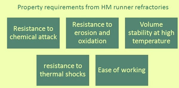
Fig 1 Property requirements from HM runner refractories
Refractory materials for runner are to be made from high purity raw materials. They are to be chemically neutral since they remain in contact with HM and liquid slag for a long time. The basic raw materials used these days for the runner refractories are fused corundum, bauxite, andalusite and chamotte. SiC and Si3N4 are added as anti-oxidation agents. Furthermore, metallic materials such as aluminum and silicon powder are sometimes needed to bind the materials. Mainly water is added as a liquid phase.
A non-toxic ramming mix and non-hazardous, low moisture castable has also been developed for use in the runners of the BF. The lining techniques for the main runners have been developed in parallel with the improvement in the quality of the runner materials from normal, monolithic materials with ramming to the very modern casting technique.
Tap hole drilling and gunning machines
The tap hole drilling and gunning machines are to be installed at places where they are safe concerning fire, dust and dirt. In addition to this, availability is to be high and maintenance easy, to avoid casting delays.
Cast house emission control
Cast house emission control in BF is not a statutory requirement in many countries. However, where such requirement is there, full availability of the dedusting system is necessary for ensuring the continuity of the BF operation. Due to ever tightening environmental legislation in some countries, a reduction in cast house fume emission has become necessary for some operators, during the running campaign of the BF. Bag filters can cause problems in terms of temperature capability, because waste air with a temperature of over 150 deg C is to be cleaned upon opening the tap hole.
Gas cleaning plant
The wet type top gas cleaning system of a modern BF usually consists of a dust catcher, the cyclone and the wet scrubber. Pressure losses occur in the dust catcher and cyclone, as well as in the venturi scrubber. Operating a BF with higher chlorine input can cause corrosion problems in the washer system. Depending on the rate, the injection of coal introduces an extra 0.2 kg/tHM to 0.3 kg/tHM of chlorine into the BF and this causes corrosion problems at the wet top gas cleaning system. This makes coating of the washer necessary, as well as additional action concerning the pH value of the water. Special attention is needed for the wear in the gas cleaning plant. Fusion cast basalt lining is normally used. A coating of acid resistant material at the entry end cone is preferred.
Charging and distribution system
BFs which are being operated with central gas flow, usually encounter high top gas temperatures in the middle. This temperature can go up to 1000 deg C. In such case cooling of the chute of the bell less top charging system is a possible solution.
The wear plate life on the bell less top chute determines the maximum time between the two stoppages of the BF. The frequency of stoppages can be extended by improving the quality of the materials used. The bell less top equipment gear box is also critical to BF operation. Problems like loss of oil from the angle adjustment gearboxes and damage to the slew ring tooth profile can take place. The design of the angle adjustment gear box is to allow replacement of the segment shaft seals during shutdown conditions.
General electronics and control system
Normally electronic and control system is not linked to BF campaign life. But, as the campaign life of the BF gets increased, the problem of corrosion and deterioration of the electronic and control system, which is expected to last the duration of the whole campaign, becomes a matter of great worry. In addition, over a long campaign, the availability of electronic spares becomes difficult, since technology in electronic field is changing at a very rapid speed.
Hence, it is advisable to have a stand by unit for critical electronic control system. This can reduce down time of the BF due to the failure of the electronic control system. This, in turn, can have a very positive effect on the BF campaign life.
Cooling circuits
In BF cooling system, build up in the pipelines reduces the flow rate and accordingly the heat transfer by conduction gets reduced. Build up in cooling circuits takes place due to internal corrosion and deposition. To avoid it, chemically treated water may be used. Acid cleaning and pressurized water jetting are also sometimes used to remove deposits from cooling pipes and heat exchangers.
Water flow rate is usually increased for improving the efficiency of cooling besides reducing the water temperature at the face of the coolers.
Measurement of blast flow rate at each tuyere
A measure of the blast flow rate at each tuyere is important when BF is being operated with tuyere hydrocarbon injection. In case there is a blockage of tuyere aperture, may be due to a large accretion, the hydro carbon injectant can combust in the tuyere stock or bustle main. This can result into extensive damage and thus requiring an immediate, possibly prolonged BF stoppage. The measurement of pressure drop across the tuyere stocks is frequently used for this purpose, with an automatic cut-off of tuyere injectant when a restricted tuyere flow is indicated.
Measurement of tuyere hydrocarbon injectant at each tuyere is necessary to enable good control of raceway conditions, for even circumferential operation. To optimize circumferential balance, it may prove beneficial to match the injectant flow to the blast flow.
Throat armour plates
For prolonging BF service life, and to reduce maintenance costs, an arrangement has been developed for changeable throat armour plates. This arrangement is in practical use in many BFs. The plates are fitted retrospectively, on top of worn throat armour. Preparations for their installation, involving pressure drilling and welding, are carried out during production, with few preparatory shutdowns, followed by a longer (typically 2days to 3 days) shutdown. A much longer shutdown would be required to repair throat armour plate in a traditional manner.

Leave a Comment