Probes, Instruments and measurements for Monitoring of Blast Furnace
Probes, Instruments and measurements for Monitoring of Blast Furnace
A blast furnace (BF) works with the principle of countercurrent gas to solid heat exchange from tuyere raceway to the stock line and of a countercurrent oxygen (O2) exchange from fusion zone to the stock line. Solid burden materials consisting of ferrous materials (iron ore, sinter, and pellets), coke, and fluxing materials are charged into the top of the furnace, while air normally enriched with O2, and sometimes with auxiliary fuels is fed through the tuyeres near the bottom of the furnace. The usual retention time of the ferrous burden materials in the furnace may be as long as 8 hours, while that of the gas is a few seconds. However, the residence time of the coke in the hearth is much longer usually ranging from 1 week to 4 weeks. The liquid hot metal (HM) and liquid slag are tapped at regular intervals through a number of tapholes situated at the bottom of the furnace. The slag is separated from the hot metal which is handled through HM ladles. A blast furnace need to be operated with high productivity and low fuel rate in a flexible, stable and high efficiency manner and must have a long campaign life.
The blast furnace is often referred to as black box because of the terms such as the furnace condition and furnace heat level which is currently in dominant use as well as since the blast furnace process has many unknown areas. The reason seems to be due to the difficulty in measurement, because, in a blast furnace, three phases of gas, solid, and liquid coexist, the reaction proceeds non-uniformly in radial direction, the process is accompanied by a time dependent variation, and the parameters to be measured are always moving in a high temperature, high pressure, and dust containing atmosphere.
Some of the probes which are generally used in a blast furnace are (i) ‘radar probe’ for burden level and burden descent speed measurement, (ii) blast furnace top gas Ignition lance, (iii) fixed ‘above burden’ probe for temperature and pressure measurements and gas sampling, (iv) movable ‘above burden’ profile meter to measure burden profiles, burden descent speed, temperature, pressure and for gas sampling, (v) movable ‘above burden probe to measure temperature, pressure, burden charging curves and for gas sampling, a(vi) horizontal ‘in burden’ probes to measure temperature, pressure, burden layers and for gas sampling. Other common probes used in blast furnace are stock line detectors, thermo-vision cameras, profile meters, probes using acoustic for top gas temperature measurement, impact probes, descending vertical probes, scanning probes, infra-red thermo cameras and tuyere probes etc.
Operation of a blast furnace has gradually changed from a purely experience based activity to an activity which is supported by the scientific and metallurgical principles. Blast furnace is no more is considered as a ‘black box’. An important part of this evolution is the introduction and use of sophisticated probes and measuring devices which transmit to the BF operator useful information on the state of the process. For the reliable running of the blast furnace, it is essential to collect various operating parameters by using these different sensing devices so that the BF process becomes transparent to the operator. A modern blast furnace is equipped with a large number of probes, instruments and measuring devices which imply monitoring of a large number of signals and these signals need to be presented to the BF operator in a meaningful way. Typical probes, instruments and measuring devices used in earlier blast furnaces are shown in Fig 1.
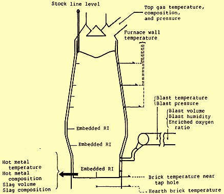
Fig 1Typical probes, instruments and measuring devices used in earlier blast furnaces
Since last 40 years to 50 years, several probes and measuring devices have been developed for the process control in the blast furnace. As a means to know the burden distribution, a vertical probe, horizontal probe, and thermo-vision camera at the throat have been developed. A combination of gas-flow distribution measurement system and burden distribution control system has allowed the controlling of blast furnace with flexibility. After these developments, the accuracy with which the burden distribution is measured and controlled has been enhanced by the utilization of various profile meters as well as a magnet meter. The development in gas analyzers has been from the conventional gas chromatography to instruments with shorter measurement intervals and with higher precision, and then toward mass spectrometers. For measurement around the tuyeres, the development has proceeded with tuyere-body thermometers, tuyere televisions, and tuyere probes that provide information on the temperature around the raceway or on gas distribution. This along with several mathematical models based on furnace heat estimation and the fusion zone estimation have helped in the improvement of the overall BF operation control system.
The signals in a modern blast furnace, which are realized through an elaborate system of probes, instruments and measuring devices for the collection of the adequate data of the total process for analysis and precise control, are very high in number. The total I/O (input-output) signals count of these probes, instruments and measuring devices can be of the order of 24,000, of this binary I/O signals can be in the range of around 18,500 to 19,000, temperature signals in the range of 1,200 to 1,500, other analog signals 4,000 and weighing signals in the range of around 70.
The probes and measuring devices of the blast furnace have made a great advancement on the basis of recent developments on electronics, optics and computer technology. With the use of computers, it has now become possible to monitor the different parameters of the blast furnace in a better way since computers allows not only displaying of the variables but also uses established models , compares different variables, and builds up data bases to store the variables and their evolution during the process.
Typical application of probes and measuring devices in a modern blast furnace is given in Fig 2.
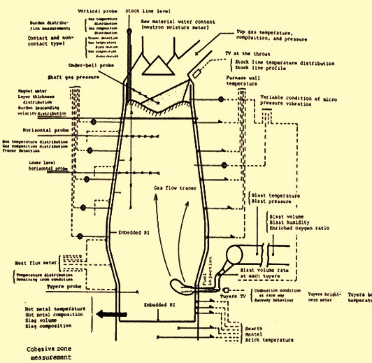
Fig 2 Typical application of probes and measuring devices in a modern blast furnace
The reactions which are taking place in a blast furnace are very complex in nature since all the three phases of gas, solid, and liquid coexist and the reactions proceed non-uniformly in radial direction. The process is accompanied by a time dependent variation, and the parameters to be measured are always moving in a high temperature, high pressure, and dust containing atmosphere and this creates difficulty in measurement. Due to the difficulty in measurement of the different parameters of a blast furnace, the furnace is generally divided in different zones. The different zones of a blast furnace and the desired measurements in the zone are described below.
Lumpy zone
In this zone indirect reduction is taking place in the furnace. The desirable parameters of the zone to be known to the BF operator are temperature distribution, gas permeability, reduction degree, speed of burden descending, and change in the physical properties of the burden. For these parameters, the measurements needed are quantity and particle size distribution, and mixed layer distribution for solid burden materials and quantity, composition, temperature and pressure in case of ascending gases. Typically the measurements which are taken are burden surface profile and layer thickness distribution, burden surface temperature, gas composition, temperature and pressure distribution.
Direct measurement in the lumpy zone is relatively easy and this allows the development of different sensors which provide much information. In this zone, the most important measurement areas are the burden distribution, gas flow distribution, and their change with time, all affecting the reduction, heat exchange, gas permeability, and descending behaviour of the burden. The three factors which help in estimating the burden distribution are (i) layer thickness, (ii) burden size, and (iii) distribution of voids. Of these three factors, only the layer thickness distribution can be measured with various profile meters. However, the capability of the profile meters is poor since they measure only the surface profile and not the changes in surface profile due to charging of burden. Further the measurements are invalid for the measurement of mixed layer. Recently a sensor has been developed which uses a magnet meter. This sensor makes the measurement possible for the changes in burden surface profile, for the layer thickness distribution including mixed layer, and descending velocity distribution.
The gas flow distribution is due to the result of the burden distribution. It is a very important measurement since it affects the operation of the blast furnace. The gas flow distribution is determined by the four factors namely (i) flow rate, (ii) temperature, (iii) composition, and (iv) pressure. The normal parameters which are measured are the distributions of temperature, composition and pressure since these parameters are easy to measure. The use of horizontal and vertical probes and furnace wall pressure gauges provide fairly satisfactory measurement values for the temperature, composition, and pressure distributions. The direct measurement of gas flow rate distribution within the burden is desirable but presently very accurate measurement methods have not been developed. Hence the gas flow rate distribution within the burden is estimated with the help of mathematical models using the data available for the gas temperature, composition, and pressure.
Cohesive zone
All the three types of reactions namely (i) indirect reduction reactions, (ii) direct reduction reactions, and (iii) solution loss reactions are taking place inside the blast furnace. All the three reactions influence the cohesive zone. Hence all the measurements which are needed for the lumpy zone along with measurements of level and the profile of the burden are important measurements for the cohesive zone.
The cohesive zone exhibits the greatest resistance to gas flow in blast furnace, and hence forms an index for the operation stability through the in-furnace gas distribution and burden descent. Therefore, measuring the position and profile of the cohesive zone is considered to be very important measurement. Presently the position and the profile of the cohesive zone cannot be measured directly and those parameters which are directly measured with various probes are used for estimating the cohesive zone by using the mathematical models.
Dripping, raceway and deadman zones
In dripping, raceway and deadman zones the activities which are taking place in a blast furnace are (i) slag formation, (ii) combustion of coke and/or auxiliary fuels, (iii) circulation of metalloids such as zinc, sulphur and alkalis, and (iv) left out direct reduction and solution loss reactions. The desired measurements in this zone are liquid permeability, metal and slag flow distribution, metalloids reaction, descend of coke, combustion of coke, deadman formation, and spreading of the raceways. Typical measurements which are being done in these zones are (i) blast volume at each tuyere, (ii) length of raceway, (iii) brightness of raceway, (iv) movement of coke, (v) size of coke, and (vi) temperature of tuyere body.
In these zones the phenomena such as coke descent, deadman formation, flow of hot metal and slag, coke combustion at tuyere raceway, metalloid reaction, and desulphurization are occurring. For better understanding of the phenomenon, gas and liquid-permeability and temperature level are thought to be important. These zones are where the final conditions of hot metal and slag are determined and hence some important information is required to be measured and understood. However, the actual measurements which are presently possible in these zones are (i) the temperature distribution of the cooling stave, (ii) the temperature of the tuyere body, and (iii) the condition of the raceway at the tuyere. The developments of measurement devices in these zones have progressed at a very slow speed, since the measuring methods in this area are difficult and also there is confusion in philosophy for what to be measured and how to arrange phenomena. For these zones, an estimation model using various mathematic models is normally used to estimate the final state of hot metal and slag as soon as possible and to control the conditions.
Hearth zone
In this zone, the collection and separation and storing of hot metal and liquid slag takes place. The only activities which take place in this zone are desulphurization and carburization of hot metal. The liquid permeability is also important in this zone. The desirable measurements in this zone are (i) level of hot metal and slag and their behaviour, (ii) coke supply and its removal because of its combustion, (iii) desulphurization and carburization of hot metal, and metalloid reaction. Typical measurements in this zone which are needed are monitoring of the behaviour of hot metal and liquid slag as well as monitoring of hearth coke replacement and for this an estimation model using various mathematic models is presently being used.
Measuring methods employed for BF process control
Some of the measuring methods presently used for the BF process control are given below.
- Distribution of burden – Measurements methods which are presently being used are (i) contact type profile meter, (ii) non-contact type profile meter, and (iii) magnet meter. Contact type profile meter measures only the burden surface profile. It neither measures change in the surface profile due to charging nor it measure mixed layers. Further there are large measurement errors especially when there is disturbed burden distribution. Non-contact types profile meters are better since it does not disturb burden distribution. In case of magnet meter, it measures the inside of burden and allows measurement of surface profile change by charging and mixed layers.
- Gas flow distribution – Measurements methods for the gas flow velocity distribution which are presently being used are (i) fluid flow meter, (ii) hot wire type gas flow meter, (iii) heated thermo couple method, and (iv) gas tracer method. Normally gas flow quantities are obtained from gas pressure, temperature and composition in case of first three methods. The gas tracer method is a momentary measurement which does not disturb burden distribution.
- Cohesive zone level and profile – Cohesive zone level and profile are measured either by direct method or indirect method. In the indirect method calculations are based on some assumptions and some measured parameters basically gas flow pressure, temperature and composition distribution. Horizontal probes are usually employed for temperature and composition distribution of gas. It is again a momentary measurement method. Gas flow pressure distribution is measured by measuring furnace wall gas pressure which is a continuous measurement without disturbing the burden. Direct measurement of cohesive zone is done by insertion type vertical probe method, RI method, and triple domain reflectometry (TDR) method. Out of the three, TDR is the continuous measurement while the other two are the momentary measurements. The vertical probe has advantage of providing data on temperature, pressure and composition as well.
Maintenance of BF shell
For a highly efficient and stable operation of the blast furnace shell and refractory lining, instrumentations are based on the inner profile of the blast furnace refractories and the maintenance of the furnace shell. Since the prolonged service life of the blast furnace greatly contributes to the cost reduction, there is the significance of the measurement for furnace shell maintenance for the purpose of giving information on the wear of the furnace refractories, scaffold build up, and for protecting the cooling equipment and the furnace attached equipment from damage.
Conventionally, the measurement of the furnace shell and refractories has been mainly of temperature with measuring points increased with expanded requirements. Recent advances in the measuring methods include an electric potential pulse method or a thermocouple response method which directly measures the refractory thickness. The BF shell maintenance also tends toward incorporating the furnace shell control system into a computer in order to cope with increased number of measuring points and with the use of a refractory wear line estimating mathematical model. Various instrumentations which are commonly used for the maintenance of BF shell and refractory maintenance are described below.
- Refractory wear and build-up of scaffold – There are several methods. The thermocouple method is the established method but the measurement points are limited and depend on the furnace temperature. The infrared thermo camera method produces graphs as a pattern and also depends on the furnace temperature. In case of the heat flux meter method, measurement points are limited and depend on the furnace temperature. Other methods are (i) thermocouple response method, (ii) potential pulse method, (iii) embedded RI method, and (iv) boring method. These methods measure wall thicknesses but does not detect an increase in wall thickness. In case of embedded RI method only one point can be measured per RI while the method of boring is difficult during normal operation.
- Protection of furnace cooling equipment – Several measurements are made for the purpose of the protection of the furnace cooling equipment and to detect damage during early stages. These measurements are (i) measurement of CO quantity dissolved in the cooling water, (ii) measurement of cooling water differential flow rate, (iii) measurement of temperatures of cooling water supply and discharge, and (iv) measurement of hydrogen in the BF top gas. The second method is sensitive to water quality. The third method tells the heat load on the cooling equipment while the fourth method does not detect the damaged portion.
- Protection of the equipment attached to the blast furnace – The equipments attached to the blast furnace are to be protected against failure. In case of gas cleaning equipment it is done by measuring and controlling temperature and pressure of the top gas while tuyeres and blow pipes are protected by measuring the blast volume and the amount of auxiliary fuel at each tuyere.

Leave a Comment