Operation practices and Campaign Life of a Blast Furnace
Operation practices and Campaign Life of a Blast Furnace
The cost of rebuilding or relining a blast furnace (BF) is very high. Hence techniques to extend BF campaign lives are important and need to be pursued very actively.
Large BFs usually have a slightly higher campaign output per unit volume. This difference is because larger BFs generally are of more modern design and well automated. Since the viability of an integrated steel plant depends on a continuous supply of hot metal (HM), which in a plant with a small number of large furnaces puts great importance on long campaign life.
The techniques for prolongation of BF campaign life (Fig 1) falls under the following three categories.
- Operational practices – The control of the BF process has a major effect on the campaign life. BF is to be operated not only for meeting the production needs but also to maximize its life. Hence it is necessary to modify operating practices as the campaign progresses and in response to the problem areas for the maximization of campaign life.
- Remedial actions – Once wear or damage that affects the life of the BF becomes evident, engineering repair techniques are to be used or developed to maximize campaign life.
- Improved designs – As improved materials and equipment are developed, these are to be incorporated into future rebuilds to extend the life of critical areas of the BF, where it is cost effective to do so.
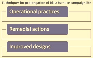
Fig 1 Techniques for prolongation of blast furnace campaign life
Operational practices for improved campaign life are discussed in this article. The operating practices affecting the BF campaign life are described below.
Productivity
The productivity of a BF is normally expressed in tons (t) of HM per unit BF volume (cum) per day. High productivity involves an increased throughput of materials at higher burden descent rates, with an increased hearth activity to remove the larger quantity of liquid products. The stability of operation is affected when the BF is being driven hard then the burden descent is less smooth and the melting zone is higher. These affect BF wall wear. The increased throughput of liquid products accelerates hearth wear and results in more arduous tap hole conditions.
Low productivity involves extended periods of low hot blast volume, which results in reduced blast penetration and an increased gas flow up the BF wall, unless suitable modifications to burden distribution are made. Long production pauses usually have a detrimental effect on hearth condition.
When considering the level of productivity on the BFs that have achieved a long campaign life, it is clear that these BFs have not been operated to their maximum potential for the majority of the campaign. The common factor is stable, consistent operation, with practices employed to monitor and protect the walls and hearth. Such operation is more easily achieved at production levels below maximum output. However, it is difficult to define a universal value of productivity index (t/cum/day) to achieve this, since the index is also affected by several factors other than driving rate of the BF. These are BF internal shape, state of refractory wear, local operating conditions, and maintenance periods etc.
For maximization of the campaign life, a strategy is needed to enable the BF to be operated in a stable, controlled manner. Many BF rebuilds have involved increasing the inner volume, not to increase output but to enable production targets to be met at lower productivity levels and hence offer the potential for more stable operation and longer campaign life.
It is a fact that frequent stoppages of a BF reduce its productivity, but the campaign life is also reduced due to the excessive number of stop/start operations. The campaign output per unit volume is reduced disproportionally to the percentage downtime. Long campaigns, measured by this criterion, are best achieved with continuous operation of BF without lengthy stoppages.
Short term reductions in productivity is also needed to attend to the problem areas identified on the BF, in order to protect the integrity of the furnace, thereby avoiding a premature end to the campaign.
Burden
For a stable operation of BF at reasonable productivity levels, good quality coke is necessary. In fact coke is one of the main reason for the poor period of operation. Poor periods of operation often results in erratic, and even chilled operations that are potentially destructive to the BF lining and hence to campaign life.
Coke need to be strong and stabilized for supporting the weight of the burden with minimal mechanical breakdown. It is to be sufficiently large and closely sized, with minimum of fines for creating a permeable bed through which liquids can drip down into the hearth without restricting the ascending gases. A consistent size is needed to avoid undesired variations in permeability and to support the concept of varying coke layer thickness across the BF radius to control radial gas flow. The coke is to be sufficiently unreactive to solution loss, retain its strength under such conditions, and be low in alkalis to minimize alkali gasification in the raceway, which has a deleterious effect on coke breakdown and on furnace refractories. Coke moisture and carbon content variations need to be controlled to minimize their effect on the thermal state of the process.
At high levels of tuyere hydrocarbon injection, there is a corresponding reduction in the proportion of coke charged and consequently coke quality becomes even more important.
A universal coke quality, for stable operation compatible with long blast furnace life, is difficult to specify, since not only do different types of operation have different coke requirements but also physical properties vary according to the point of sampling between the coke ovens and the BF.
In case of use of coke from more than one source, either adequate blending is needed or charging discretely the different cokes is essential, as fluctuating proportions of cokes of different properties results in unstable conditions in the BF.
Coke in the BF centre gradually replaces the dead man and the coke in the hearth, which must remain permeable to allow the liquids to drain across the centre of the hearth. This avoids excessive peripheral flow of HM in the hearth which can result in severe refractory wear at the base of the sidewall. An increase in the hearth pad centre temperature is usually being observed with an increase in dead man coke size, which indicates increased hearth centre activity. The aperture size of the coke screens is an important parameter for the maintenance of the hearth permeability. It is usually beneficial to increase the screen size and charge the additional small coke arising, mixed in with the ore burden, away from the BF centre line.
The aim of using high quality coke is to ensure that large coke reaches the lower regions of the BF. For monitoring this, it is desirable that the coke is sampled from time to time at tuyere level for assessing the coke breakdown through the furnace. This is normally carried out during the planned maintenance. A large sample of coke is raked from a tuyere aperture and its properties are compared with a sample of the corresponding feed coke. In this way other factors affecting coke size can also be identified.
Good, consistent quality coke and the monitoring of both stock line and bosh coke is clearly an important strategy for long campaign life.
Ore burden mix
BFs are being operated with a wide variety of ore burden components such as sinter, pellets and sized iron ore (SIO) etc. A variety of fluxes are also used in the ore burden.
Smaller quantities of other materials such as recovered scrap, ferrous fines, mill scale, converter slag, ilmenite, recycled waste or even directly reduced iron or granulated iron are also sometimes used in the ore burden. The use of these materials usually depends on local factors.
Integrated steel plants normally have sinter plants hence BFs in these plants use a large percentage of sinter in the burden, with the balance of the burden consisting mainly of SIO and/or pellets. Pellets are preferred over SIO in some plants for the balance of the burden because of their superior properties.
Around the world, pellet percentage in the BF burden vary from 0 % to 100 %. Experience in different plants has shown that BFs using a high percentage of pellets suffer higher heat load variations in the lower stack and bosh, leading to excessive lower stack and bosh wear and a shorter campaign life. One of the reason for this is the inadequate control of burden distribution. Pellets have a much lower angle of repose than sinter or coke and, when landing on an inclined stock line, tend to roll easily. This results in a relatively thick ore layer towards the BF centre which encourages excessive gas flow at the wall of the BF.
This situation is being countered with the addition of high density cooling in the lower shaft and improved burden distribution equipment. Fluctuating lower stave temperatures, increased slipping and HM temperature fluctuations can be observed with pellet charge which is to be controlled by burden distribution control, with centre coke charging and addition of nut coke to the pellets.
An important aspect of the individual burden component is the softening and melting characteristics. The major part of the pressure drop across a BF is in the region where the ore burden is softening, melting and dripping down the coke bed through which the gases are ascending. A wide melting and softening range causes an increased pressure drop and a large cohesive zone root impinging on the lower shaft brickwork, with the refractories being exposed to high temperatures over a wider area than is desirable. A lower wall temperature and/or fewer thermal fluctuations help to prolong the life of the shaft brick work.
The melting and softening properties of a multiple component burden differs from those of the individual components. Hence the softening and melting test data is to be considered not only for the individual burden constituents but also of the proposed ore mix for aiding the ore burden selection.
For minimizing thermal and chemical variations, a homogeneous burden is desirable. The burden components should be as intimately mixed as possible. This depends on the number of burden components and the individual charging system, but it can usually be achieved to a reasonable degree by selection of storage bunkers and the sequence of material discharge.
It is possible to achieve stable BF operation and long campaign life using different burdens provided the material quality is consistent and there are available adequate wall cooling capacity and proper distribution control.
Quality of ore burden
A permeable BF is necessary for stable operation. It is important that the ore burden is strong, closely sized and efficiently screened to remove fines. It must not disintegrate excessively in the stack and generate additional fines. It must be sufficiently porous, reducible and of size which allows it to be effectively reduced by the time it reaches the softening zone. In this way the cohesive zone is less restrictive, with less FeO rich slag, and the thermal load in the lower regions of the BF is lower, encouraging smooth operation.
The softening and melting properties of the ore components have an important effect on the operation of the BF. Restrictions in the cohesive zone and poor melting characteristics can result in erratic burden descent, unstable operation and thermal fluctuations. These conditions are likely to shorten the BF wall life.
There is no standardized softening and melting test and there are many indices quoted to represent the softening and melting temperatures such as start of direct reduction, pressure drop during melting, and quantity of dripped material etc.
Burden distribution
Burden distribution is one of the main factors which affects the campaign life of the BF. Not only can it affect the stability of operation but, by determining the radial gas flow in the BF, it is one of the major factors controlling the rate of wear of the BF walls.
Generally radial gas flow is controlled by the ore to coke ratio in the burden, since coke size is usually larger. This is normally achieved by charging the material in discrete layers and varying the layer thickness across the radius of the BF. Protection of the BF walls is therefore achieved by increasing the proportion of the ore layer at the wall, which results in a reduced quantity of heat removed by the wall cooling system. However, there is a limit to the proportion of ore material close to the BF wall to avoid the formation of an inactive layer, which may encourage the formation of wall accretions and allow unprepared burden into the lower regions of the BF and increase the tuyere losses. The proportion of coke at the centre of the BF must be sufficient to allow stable BF operation at the desired level of production. A large proportion of coke creates a relatively permeable region with fewer descending liquids, allowing the use of maximum blast volume without large fluctuations in blast pressure and erratic burden descent.
The coke at the centre of the BF replaces the coke in the hearth and a coke rich permeable centre encourages a permeable hearth, which relates the liquid flow across the hearth. The central coke chimney is not to be unnecessarily wide. In such a case inefficiency results and damage may be incurred to certain parts of the furnace top due to excessively high heat capacity of the ascending gas.
Split size charging
More sophisticated distribution systems permit additional control of burden distribution by utilizing more than one size range of a given material. One of the most commonly used practices is the charging of fine ore materials, often from screenings of the main ore burden. Fines are charged separately in small quantities close to the BF wall, to give a localized reduction in permeability and thereby protect the walls. Charging a separate small batch of finer material usually reduces the charging capacity of the BF.
Nut coke
A flexible charging system allows the use of nut coke nut (typical size is in the range 10 mm to 30 mm). The charging of nut coke, mixed in the ore burden and positioned along the mid radius, improves operation by improving reduction efficiency and permeability of the ore layer in the cohesive zone. There is improved permeability and reduced belly temperatures with nut coke charging. The nut coke charged at the wall, sandwiched between the two ore charges prevents an inactive wall region when fine ore was charged at the wall. Nut coke is added to the pellets to increase their angle of repose, thereby reducing the proportion of ore burden at the BF centre.
Size segregation
Many charging systems create some degree of size segregation in the input materials. If the initial material to discharge is finer and the final material is coarser, this characteristic may be utilized to benefit the radial size distribution, and hence the radial gas flow distribution. This type of segregation generally occurs on belt charged furnaces rather than on skip charged furnaces and is more controllable with a bell less top. Suitable modifications can also be added to the charging system to enhance the desired segregation characteristics.
Additional radial size segregation can also occur by rolling down an inclined stock line. Size segregation can also modify the melting and softening characteristics of the burden along the BF radius, when one component has a different size range and chemistry.
Some charging systems results in a circumferential variation in burden distribution. These variations are to be minimized by design or operation.
Centre coke charging
A large proportion of coke is usually needed at the BF centre, to encourage sufficient centre working for stable operation. This is particularly so at higher productivities and when operating with high levels of tuyere hydrocarbon injection. However, to operate with entirely coke in the centre of the furnace is less fuel efficient and techniques have been developed to minimize the width of this region of the centre coke charging. On a bell less top, this is achieved by charging a small batch of coke with the rotating chute fully lowered.
A permeable coke bed is necessary in the hearth, to encourage the flow of liquids across the centre of the hearth and reduce peripheral flow, which can cause excessive sidewall wear. The coke in the dead man and hearth is gradually replaced by coke from the furnace centre. Centre coke charging reduces the percentage of ore material at the BF centre and improves hearth permeability. Hearth permeability can be further improved with larger stabilized coke charging at the centre.
Throat armour life
For long campaign life, it is important to minimize wear on the fixed throat armour caused by the direct impact of burden materials. Although it is possible to repair the throat armour or incorporate protection plates, this may involve long maintenance stoppages, which themselves may be detrimental to the furnace life. Hence the burden distribution and the stock line height used are to be chosen to avoid such burden impact.
Hot metal quality
When operating without a protective skull in the hearth, the hearth carbon is usually removed by solution attack of iron and slag. Early carburization of the iron, before it contacts the hearth refractory minimizes such hearth wear.
For early carburization, an extended period of contact between liquids and coke is needed. At a given productivity, this may be encouraged by a taller dripping zone and dead man, with a higher cohesive zone. This normally results in an increase in HM silicon (Si). Generally the carbon saturation level decreases with increasing Si content. As a result, HM is closer to saturation at higher Si levels, for a given BF size and the HM temperature.
In addition, an increase in HM Si increases the HM liquidus temperature and thereby reduces its fluidity. This tends to reduce the flow velocity in the hearth and encourage the formation of a solidified layer on the hearth refractory.
At lower HM temperatures, the carbon saturation level of the iron is lower and is achieved earlier. Low HM temperature has the added benefit of increased iron viscosity which reduces peripheral flow, reducing the tendency to dissolve protective skulls and penetrate fine cracks and pores.
Higher HM Si and lower HM temperature are difficult to achieve together, as a higher cohesive zone usually results in a warmer furnace, but the overall effect is for the HM entering the hearth to become closer to carbon saturation. A reduction in high top pressure is likely to result in a slight increase in Si without affecting the thermal state of the BF. The probability of dissolution of hearth carbon is lower at higher Si levels.
Tuyere diameter
Tuyere diameter is chosen to ensure adequate blast penetration for given operating conditions and to prevent excessive gas ascending the BF walls. The selection of tuyere size influences the degree of centre working of the BF and the degree of protection of the bosh and lower shaft walls. It is usually necessary to vary the tuyere diameter around the BF to ensure circumferential balance of gas flow.
Although tuyere sizes are carefully chosen, a significant increase in diameter is often observed when a tuyere is changed, particularly when long lives are achieved. This affects both of the above factors and it is advantageous in terms of campaign life to change tuyeres after a given period, not only to minimize the effect of tuyere wear but to reduce the likelihood of water leakage into the BF and the number of unscheduled off blast periods to change failed tuyeres.
The diameter of tuyeres directly above the tap hole is often reduced, or the tuyeres even closed, to promote smooth casting and reduce the iron make above the tap hole.
Tuyere diameter is often reduced locally, in response to high hearth sidewall temperatures, to reduce the dripping liquids and hearth activity in the problem area. This is done by the addition of tuyere inserts or by tuyere replacement. In severe cases, or as a short term emergency measure, the tuyeres in question may be closed by plugging with clay. This often has a rapid effect in reducing the corresponding hearth sidewall temperatures.
Cast house practices
Cast house practices play an important part in controlling liquid flow in the hearth and avoiding high liquid levels which may impinge on the raceway, affecting blast distribution or even causing tuyere or blowpipe damage. These factors can affect the stability of operation, result in periods off blast and potentially affect campaign life.
Tap hole length
With a longer tap hole, the molten products are not only drawn from lower in the hearth, but also from a point closer to the centre of the hearth. This reduces peripheral flow near the tap hole and hence wear of the hearth sidewall. To extend tap hole length, it is necessary to increase the quantity of tap hole mass injected over a period of time, to progressively increase the size of the mushroom on the inside of the BF, which also protects the refractory below the tap hole. With a short tap hole length and casting alternately from widely spaced tap holes, sidewall temperature fluctuations increases, potentially increasing refractory erosion.
High hearth pad temperatures may be experienced due to the loss of a frozen layer and/or hearth carbon dissolution, whilst hearth sidewall temperatures are satisfactory. In such cases, it may be necessary to shorten the tap hole, by decreasing the quantity of tap hole mass injected and possibly by a reduction in the tap hole inclination. This helps in the reduction of HM flow near the BF centre and increase the liquids retained on the hearth pad.
Tap hole diameter
The tap hole diameter necessary to sustain a given productivity depends on the BF parameters, such as the proportion of time casting, top pressure, slag volume, hearth coke size, liquid viscosities and the properties of tap hole mass. In case the tap hole is too small for a given production rate, then it will not be possible to cast the furnace dry. If the tap hole is too large, fewer molten products may be removed from the furnace during a cast as the tap hole will blow prematurely, since the liquids above the tap hole gets removed before the liquids on the opposite side of the hearth can descend through the coke bed. In both of these cases, the liquid level in the hearth remains high and ultimately affects stable operation. Hence the optimum size of tap hole is necessary which is arrived at from experience.
When a single tap hole is used, the size must be chosen to enable the BF to be cast dry and provide sufficient time for the tap hole mass to cure between casts. On a BF where alternate tap holes are used, different sized tap holes may be needed under certain operating conditions, to ensure drainage across the furnace.
On a multi tap hole BF that is experiencing wear in the hearth pad, it may be desirable to increase the tap hole diameter. This, together with a decrease in tap hole length, reduces the iron flow across the hearth pad and increases the residual iron in the hearth at the end of cast, thereby encouraging the formation of a frozen layer on the hearth pad.
Tap hole mass
The tap hole mass properties are important for the BF operations. The mass must set rapidly and cure fully between casts to create a strong, durable tap hole. The tap hole mass must have good adhesion properties, to build up a strong, permanent structure that resists the flow of liquids and also protects the hearth refractories below the tap hole.
Number, position and performance
High productivity can be attained on a medium sized, single tap hole blast furnace. However, there are advantages when more than one tap hole is available, this being a necessity at higher production levels. Alternate casting from tap holes on opposite sides of the furnace results in more effective hearth drainage, and also gives a longer period for the tap hole mass to cure fully, resulting in a more durable tap hole. The existence of two tap holes allows major refurbishment of a main iron runner without requiring a period off blast. If hot spots occur on the hearth wall of a multi tap hole BF, it may be possible to use an alternative tap hole which does not encourage peripheral flow in the eroded area. Sidewall wear resulting from peripheral flow will be spread more evenly around the circumference on a multi tap hole furnace.
For a large, high productivity BF, it is preferable to have four tap holes, allowing an opposite pair to be operated whilst one runner is repaired and the other is on standby. To even out sidewall wear and encourage complete hearth drainage, these would ideally be located at 90 deg intervals.
Casting frequency and rate
Casting rate is determined by the tap hole drill size used, the wear characteristics of the tap hole mass, top pressure, the viscosity of the liquids and the number of tap holes in use. With modern high performance tap hole mass, there is a tendency to reduce the number of casts, which reduces the tap hole operating costs. By lowering the casting rate, the liquid velocities within the hearth decreases but they continue for a longer period. On a multi cast house BF, the possibility exists to cast from opposite tap holes simultaneously (lap casting), providing the tap hole mass cures fully in a shorter time than the cast duration and the manpower and logistics enable it. This technique reduces the flow velocities in the hearth, although it is often only used in times of high liquid level or before taking the BF off blast.
Lengthy casting delays must be avoided at all costs, to minimize disruption to BF operations. This requires good design and reliable operation of cast house equipment, good cast house practices and well coordinated transport of HM ladles.
Alkalis and zinc
Alkali metals and zinc have a deleterious effect on the BF process and refractories. The burden is to have alkalis and zinc content at a minimum economic level. Normally alkali and zinc are controlled at levels of less than 5 kg/tHM (best practice being 2 kg/tHM), but by the condensation of alkali vapour on the descending burden a large recirculating load can build up in the BF. This results in increased sinter degradation and coke breakdown, and encourages the formation of wall accretions, all of which can result in irregular burden descent and unstable operation of BF.
Alkalis and zinc, in gaseous form, penetrates cracks and pores in the BF wall refractories. The resultant chemical attack and thermal cycling weakens the surface layer of refractory, which is eventually removed by the descending burden, allowing the process to be repeated.
Hearth dissections after the end of campaign have shown that excessive wear occurs at the base of the sidewall and that a brittle zone is usually formed between the shell and the hot face of the carbon. Alkalis and zinc are often found at high levels in this brittle zone. Various breakdown mechanisms have been proposed involving these compounds. Stress and thermal cracking in the sidewall allow gaseous alkalis and zinc to penetrate and get deposited in the pores. This leads to brick expansion, embrittlement, further swelling and ultimately destruction of the refractory mass. A significant degree of refractory protection from alkalis and zinc is achieved if an accretion or skull is frozen on the hot face of the refractory, thereby protecting the refractory from chemical attack.
The majority of the alkalis are removed in the slag and the remainder in the top gas. However, the slag practice, thermal state and burden distribution play a major role in alkali removal. A reduction in slag basicity increases the quantity of alkali removed in the slag as an increase in the thermal level of the BF or in the top temperature, by broadening or intensifying the degree of central working. In addition, for a given alkali loading, coke degradation is likely to be greater for operations with a high rate of tuyere hydrocarbon injection, due to the increased burden residence time. It is important that the balance of input and output of alkali and zinc is monitored and that the BF is operated with a thermal and chemical regime compatible with the input level of these elements, to encourage their removal in the slag and top gas.
TiO2 addition
Samples of the hearth lining at the end of a campaign in BFs normally contain titanium bearing deposits. These form a protective layer in eroded regions of the hearth side wall, in the salamander and in brick pores and joints. The titanium is usually in the form of carbonitrides Ti(C,N), a solid solution of titanium carbide (TiC) and titanium nitride (TiN). Hence presently practice involved to introduce titania (TiO2) into the BF to promote these protective layers. Three methods are normally used for the introduction of TiO2. These are (i) addition to the burden, (ii) injection at the tuyeres, (iii) addition through tap hole mass.
The most common technique has been by the addition of titaniferrous ores (usually ilmenite) to the burden. Alternatively TiO2 can be added through sinter, though at low levels.
Two strategies are generally adopted for TiO2 addition. The first one is remedial, commencing TiO2 additions only when high hearth temperatures are observed, indicating hearth wear. The other takes a preventive approach and adds a small quantity of TiO2 continuously, increasing the addition level if high temperatures are observed. The TiO2 intake for the preventive approach is generally 3 to5 kg/tHM, which usually results in up to 0.1 % Ti in the HM and 1 % to 1.5 % TiO2 in the slag. For remedial action, the TiO2 dosage can be up to 20 kg/tHM, at which level the HM may contain up to 0.3 % Ti and the slag up to 3.5 % TiO2. This creates operating problems due to high slag viscosity and scaffolding in the runner, and hence such high TiO2 levels are only used for short periods.
For promoting the precipitation of Ti(C,N), sometimes the TiO2 addition is increased before a shutdown so that the HM remaining in the hearth get saturated in Ti. As the hearth cools during the shutdown, this promotes precipitation. However the resumption of production is more difficult at high Ti levels as it creates operational problems.
TiO2 can also be added by injecting TiO2 fines through the tuyeres. The advantages of the technique are (i) application at localized positions, (ii) reduced cost due to lower TiO2 rate, and (iii) good results from short time injection, and (iv) unchanged burden properties.
The third method of TiO2 addition is by the use of tap hole mass containing TiO2. One such mass which had been tried was tar bonded with approximately 10 % TiO2. Clearly, the titania is bound in the tap hole mass in an unreduced form, and is injected in relatively small quantities. However there are doubts whether it gets reduced and dissolves in HM in sufficient quantities to be precipitated or whether it is reduced and bonded adequately to the hearth sidewall to be of benefit.
TiO2 is normally partially reduced in BF and is dissolved in the HM. The solubility is greater at higher temperatures. If the Ti in the HM is nearing saturation and the refractory hot face temperature in eroded regions, cracks and pores temperature is lower than the HM temperature, then Ti is precipitated, as Ti(C,N). The technique is more likely to succeed at higher addition rates, but there are other factors which can interfere with this basic mechanism, including thermal state of the hearth, metal/slag chemistry and liquid flow characteristics.
TiO2 additions is usually carried out in conjunction with other remedial actions such as reducing productivity, closing tuyeres and improving hearth cooling intensity. The direct effect of TiO2 addition is therefore often difficult to determine. It is essential to carry out regular, accurate Ti balances to assess the technique and modify operation to encourage Ti retention. The effect of high rate additions can even have a detrimental effect on furnace operation, negating any benefits.
The addition of TiO2 for hearth protection is normally to be considered as part of a hearth protection plan rather than in isolation.
Monitoring
Burden distribution is to be monitored regularly for ensuring the wall protection and a stable and driving BF. Changes in the operating parameters, e.g. changes in tuyere hydrocarbon injectant rate or blast volume, may need adjustments to burden distribution. The effect of burden distribution is usually monitored with various probes and instruments.
For maximizing the campaign life, it is necessary that the charging equipment is capable of controlling accurately the burden distribution. Also necessary instrumentations are to be fitted to comprehensively monitor the BF operation so that the burden distribution is changed and assessed in a controlled and technical manner.
Instrumentation and control
Early warning of hearth problem areas is vital to maximize campaign life, and thermocouples located in the hearth sidewall and in the hearth pad are absolutely necessary to monitor hearth wear. Revised operating practices and actions to protect the hearth are to be taken as a result of increasing hearth temperatures. Hearth pad and sidewall temperatures can also give an indication of liquid flow in the hearth, an important factor in hearth wear.
Temperatures recorded by thermocouples are influenced by only a small area round the thermocouple. It is therefore vitally important to locate the thermocouples in the critical wear areas. Important areas are below the tap holes and around the base of the sidewalls where the so called ‘elephant’s foot’ wear pattern is normally found. An adequate number of thermocouples are to be installed, in the best layout to give as complete coverage as far as practical. At several locations, thermocouples can be positioned at two or three different depths to allow calculation of the thermal profile in the refractory and hence the thickness of residual refractory.
Movement of carbon blocks can nip hearth pad thermocouples, causing false hot junctions or total failure. These problems can be overcome by fitting the thermocouples in sheaths. Thermocouples are also to be positioned around the tap holes, to monitor tap hole conditions and operation.
Additional thermocouples are often added part way through a campaign in areas of known refractory wear, to give a more localized picture of developing problems. Similarly, thermocouples are often added to repaired areas to monitor the repair.
Monitor hearth cooling
Heat flux in the hearth pad or stave cooling water can be determined from the water flow rates and the difference between inlet and outlet water temperature, using resistance thermometers. It can be used only to give an indication of the average hearth wear. It is particularly applicable in the later stages of a campaign, following thermocouple deterioration. Monitoring long term trends in hearth cooling water temperature may give an indication of the efficiency of the cooling system.
Furnace wall conditions
The process conditions at the furnace wall are vital to campaign life. The walls is not to be subjected to high heat loads from an excessive quantity of gas ascending at the wall or impingement of the melting zone on the wall, which results in rapid deterioration of the refractory and wear of the cooling members. On the other hand the walls must not be so inactive that large accretions are permitted to form on them, which prevents smooth burden descent, control of burden distribution and stable blast furnace operation. To monitor wall conditions a variety of methods are used.
The common method of monitoring the walls is using in-wall thermocouples, positioned in the brick work, with the tips a short distance back from the hot face to give a good thermal response. Wall activity is monitored from the temperature level and fluctuations.
There must be a good coverage of thermocouples both vertically and circumferentially to monitor the walls adequately. Typically seven levels of thermocouples, each with eight circumferential positions are used. With a large number of thermocouples, it is difficult for the operator to monitor the variation of them all. By using the temperatures at many points, an isothermal map is normally generated, identifying regions of high or low temperatures which relates to refractory wear, asymmetrical operation or accretion formation. The dynamic temperature behaviour is also be utilized to predict the formation or loss and extent of an accretion.
Throat or skin thermocouples are often installed around the periphery, just below the fixed throat armour. The thermocouple tips are installed level with the hot face of the refractory, to record gas temperature. These give a direct measure of the gas flow at the wall and are usually unaffected by deposition of material, unlike in-wall thermocouples lower in the stack.
Radial measuring probes
The use of retractable probes is one of the important techniques to monitor and optimize burden distribution, and hence campaign life. Such probes are the only method of measuring the variation in operating characteristics along the furnace radius, as opposed to relying solely on wall measurements. They are essentially of two types namely (i) overburden, and (ii) underburden.
Overburden probes have several functions. The simplest type is usually fixed, water cooled and measures the radial or diametrical top gas temperature profile and, in some instances, the gas analysis. Most retractable probes measure the stock line layer profile and can be of a mechanical type, where a weight is lowered to the stock line or a non-contact type, using radar, microwaves, lasers, etc.
Top gas velocity can also be physically determined to measure the quantity of gas flow, and top gas analysis and temperature measurement is frequently carried out in conjunction with the other functions. Probes are also used to determine the trajectory of material off the rotating chute or movable throat armour, for calibration of burden distribution predictive models and to determine the effect of charging chute wear.
Underburden, or in-burden, probes sample gas and measure temperature at a number of radial positions. They are generally positioned in the upper stack, typically 3 m to 6 m below the stock line. These probes are generally of two types. The consumable type, is typically 50 mm in diameter, bends with the descending burden and is straightened on withdrawal for subsequent re-use.
Since the top gas has to pass from the stock line up one of the four off takes, the gas flow pattern begins to distort near the stock line. A large degree of gas mixing then occurs above the burden, and overburden probes must be positioned close to the stock line, and preferably inclined, to give acceptable temperature and gas profiles. The upper stack underburden probes are more sensitive and give superior results to overburden probes. In addition, fixed overburden probes can be quite big in size and, depending on the stock line height, can create a ‘shadow’ and distort the burden distribution below them, which can give unrepresentative results.
Probes, especially underburden probes, are essential tools for prolonging BF campaign life.
Hearth models
In recent years, with increasing computing power available, many mathematical and numerical techniques have been developed to predict blast furnace hearth erosion and liquid flow in the hearth.
Hearth lining wear may be calculated by mathematical model, using temperature measurements from embedded thermocouples in the hearth bottom and sidewall. For this technique to be accurate, a good coverage of thermocouples is required and their depth of insertion needs to be known precisely, together with the thermal properties and geometry of the lining. The accuracy may also be affected by parameters that may change with time, such as the conductivity of ramming, thermal contact between courses of brickwork and the development of a brittle zone in the refractory, which can significantly change its conductivity.
Although hearth temperatures alone give a direct indication of hearth wear, this type of modelcombines information from the thermocouples, at differing distances from the hot face, to predict the extent of wear and solidified layers more accurately.
Direct measurement of hearth lining wear is difficult and undesirable since this requires test borings and embedded sensors through the full refractory thickness.
Artificial Intelligence
The blast furnace process is a complex one, with a large number of process variables. Modern, well instrumented furnaces have hundreds of sensors which require to be monitored by a decreasing number of operators. Consequently, computerized systems are being developed to process the primary information available and give secondary advice to the operators. This is based on a set of operating rules, statistical analysis of data, identifying trends that compare with historical data and use of intelligent techniques such as fuzzy logic and neural networks. The aim of these systems is to predict deviation from steady operation and to quantify the change in control parameters required to minimize the deviations in production and quality. This results in more stable BF operation, avoiding major operating problems such as erratic burden descent and chilled conditions, which is a primary requirement for long campaign life.
Furnace top sensors
Since the late 1970s, many BFs have been equipped with infra-red cameras viewing through windows in the top cone, to measure stock line temperature profile. This technique overcomes some of the disadvantages of fixed overburden temperature probes. The falling burden is not scattered as with probes, leading to a more symmetrical burden distribution, and by measuring material temperature the effects of stock line to probe distance, which can result in gas mixing and desensitizes the temperature profile, are avoided. A further benefit is that the rotation of the distribution chute in the furnace can be observed. However, these systems are expensive, difficult to maintain and experience problems in keeping the viewing window clean, due to the moist, dusty top gas. Problems have been experienced with the dust in the top gas also affecting the temperature distribution. Hence these cameras are not a standard fitment and many operators have abandoned them in favour of radial probes.
Some furnaces are equipped with non-contact stock line profile measurement systems installed in the furnace top cone. These systems effectively replace a retractable overburden probe and, although expensive, have the advantage that they measure over a larger proportion of the stock line than the single radius of a probe.
Thermography
The use of thermal imaging cameras to detect hot spots, on the furnace shell, top gas system, tuyere stocks, stoves, hot blast and bustle mains and other ancillary plant, is important. Not only does it enable early detection of problem areas and permit their systematic rectification, but it also helps prevent catastrophic failures, in which the BF has to be taken off-blast in a sudden uncontrolled manner followed by an often difficult recovery, which would have a detrimental effect on campaign life.
Leak detection
An efficient system of detecting water leaks into the BF from tuyeres and other cooling members is essential. Undetected water leaks may chill the furnace, resulting in erratic operation and difficult recovery from chilled conditions. Water leakage directly affects BF campaign life if it damages the refractories. Water leaks in lower, hotter regions of the BF, which are lined with carbonaceous materials, inevitably results in oxidation of the refractories. Rat holes in the hearth refractories can result, which can lead to breakouts. Water leakage can also result in tap hole problems which may disrupt operations.
Tuyere leak detection systems are often used. One leak detection system incorporates a system of magnetic flow meters with computer analysis of the differential flows. Another system of leak detection uses a pressurized closed circuit water system incorporating make up tanks with the makeup frequency indicating the severity of a leak. Other systems involve observation of gas bubbles or dissolved CO content in the water, differential pressure measurements etc.
A good leak detection system often warns the operator of a water leak in its early stages, before an immediate off blast is required. This gives the opportunity for the leaking member to be isolated prior to the furnace being taken off in a controlled manner, with reduction in tuyere hydrocarbon injection and ore/coke ratio adjustments, thereby minimizing detrimental effects resulting from the subsequent stoppage.
Plant maintenance
All maintenance work possible are to be carried out during production, thereby reducing the off blast time necessary. To minimize the duration of a planned stoppage, good planning and advance preparation are necessary. Although these factors are obvious for economics and to maximize plant output, their long term effect on furnace life is not always considered.
Preparations should always be in hand for maintenance to be carried out if the furnace comes off blast unplanned for other reasons. For instance, if the furnace is off for a tuyere change, it may be possible for work to be carried out on the charging system. If the furnace is off blast for problems at the steel melting shop, then it may be possible for more extensive maintenance to be performed. In this way, the total number of stoppages during a BF campaign can be reduced and their duration minimized.
Effective maintenance reduces the number of breakdowns which result in unplanned stoppages. This involve routine maintenance, regular inspections, periodic checking of important instrumentation, and condition monitoring, e.g. vibration and thermal monitoring. This is most important at later stages of a campaign, as ancillary equipment gets older and less reliable.
Similarly, improved cast house maintenance techniques can reduce off blast time, e.g. extension of the life of the main iron runner on a single tap hole furnace reduces downtime.
Off blast periods
The number of off blast periods, mainly unplanned ones, has a major effect on campaign life in terms of output per unit volume, which is reduced disproportionally to the percentage downtime. Wall damage can result from an increased degree of wall working at the lower blast volumes encountered whilst coming off and on blast, cooling and reheating of the refractories or erratic operation during recovery from the stoppage.
Some BF operators indicate that off blast periods ‘rest’ the hearth and allow a protective skull to form or thicken. In fact, taking the BF off blast is often an emergency procedure, at later stages of the campaign, when high temperatures are detected within the hearth refractory.
Short stoppages
For planned stoppages, additional coke can be charged several hours in advance, to compensate for the reduced blast conditions and the heat losses during the stoppage period. This extra coke in the lower regions of the BF assists smooth recovery from the stoppage. It is usual to decrease or remove tuyere hydrocarbon injection for a stoppage.
At high injection rates, there is a much lower proportion of coke in the BF, which is consequently less permeable and this may hinder recovery from the stoppage. In addition, at high injection rates, the BF is markedly fuel deficient during the recovery until the injection is resumed. This may not happen until the blast volume has reached about half of its full rate, when an adequate raceway is formed and the injectant can be consumed safely. In case there are operating problems in establishing raceway conditions and returning to the level of blast at which injection is possible, it can result into cold conditions or tuyere blockages with slag and the BF is fuel deficient at a time when additional fuel is needed.
In addition to ore/coke ratio compensation, a burden change is generally desirable for a stoppage period. Smaller material components of the burden is to be removed from the burden to promote permeability following the stoppage. High levels of titaniferrous ores is also to be reduced to avoid problems at lower HM temperatures after the stoppage. The proportion of burden components that deteriorate when at high temperatures over a long period, such as ores prone to decrepitation, are to be reduced in a stoppage burden. In addition, a more acid burden may be charged to compensate for higher Si content in the HM during recovery from the shut down.
During a stoppage, other deleterious factors can occur which affects the return to full blast operations. For example, this may include (i) extended periods at reduced blast volume to cast the furnace dry before the off blast, (ii) an extended stoppage period for a variety of reasons, (iii) water leakage into the BF during the shutdown, and (iv) problems during the recovery that may require several off blasts (may be to rectify blast leaks or charging faults etc.). Under such circumstances, the undesirable operating conditions are extended and the additional coke charged may not be adequate, leading to a less smooth recovery from the stoppage.
To ensure smooth operation and minimize the effect of a stoppage on the life of BF, some operators believe a slow start after a planned stoppage. A typical of this is to control output to 90 % on the day before a stoppage and resume at 80 %, then 90 % output on the two days following the stoppage. However, this may not be acceptable to other operators, under conditions where high output is needed.
Unplanned stoppages are undesirable and, if possible, many BF operators try to delay taking the BF off blast for long enough to allow a compensated burden to descend to bosh level. Attempt is usually made to cast the BF as dry as possible, to avoid getting slag back into the tuyeres and blowpipes, which may freeze and further prolong the stoppage. This also gives time to prepare for the repair work due to be carried out and to minimize the time of off blast. To compensate for the heat lost due to an unplanned stoppage, the tuyere hydrocarbon injection is generally increased after coming back on blast, providing it is not already at its maximum level.
Production stoppages can also occur due to the problems in the steel melting shop or during periods of low demand. These occurrences are to be coordinated so as to get advanced warning wherever possible, and to give the option of a compensated burden. The pig casting machine (PCM), torpedo ladle fleet or steel melting shop mixers are to be used as a buffer for short stoppages. In certain circumstances, when there is minimal advance warning of a shutdown, the BF is not dry and there is little empty ladle capacity, and there is no PCM available, it is preferable to dump the HM.
Stack spray techniques for the repair of wall refractories have advanced, enabling the walls to be gunned in a relatively short stoppage, by blowing the burden down to a low level. Although this allows a large quantity of coke to be charged at the lower levels of the furnace to aid start up, there is often difficulty due to the quantity of rebounded refractory falling into the furnace. Start up is easier if a low rebound material is used and the BF is blown down to tuyere level, enabling the rebound material to be raked from the furnace. This can be achieved more effectively by the use of T shaped sheets of corrugated sheeting, inserted rolled up through the tuyere cooler apertures. The blow-in burden chemistry is also to be adjusted to give a slag chemistry that enables the residual rebound material to be melted.
There is a difference of opinion as to whether or not cooling water flows should be decreased for stoppages of greater than a given duration. Some operators prefer reduced flows to maintain refractory temperatures. The majority prefer the hearth cooling water on full flow to promote a thicker protective skull, whilst others who reduce the water flow suggest that by removing less heat it assists a smooth start up.
Another factor which affects the recovery from a stoppage is the removal of an accretion from the BF walls, resulting from the additional wall working and erratic burden descent. This can results into chilled conditions at a time when they are least desirable. If an accretion is known to have formed, it is desirable to try and remove it before a long stoppage. A good system of accretion monitoring provide immediate warning in case of its occurrence, to enable thermal compensation as soon as possible.
Long stoppages
Depending on the duration of the stoppage, the BF may be filled with a coke blank and a low ore/coke burden, or the burden may be blown down to tuyere level. For stoppages of several weeks or longer, the salamander is to be tapped. If this is not done, not only will a considerable amount of process heat be needed, during the recovery, to melt it, but it will expand whilst still solid and create undue stresses on the hearth refractories and shell, shortening their life. This is even more important with those BFs, where the sump depth has been increased to reduce peripheral iron flow in the hearth. It is desirable to monitor these stresses with strain gauges attached to the hearth jacket, and to develop procedures to minimize such stresses.
To recover from longer stoppages, when the BF is in a cold condition, it is necessary to’ warm the hearth and establish an early link between the tap hole and the tuyeres to allow liquids to be removed. This may be done by the use of a blast pipe at the tap hole or the use of an oxy-fuel lance. It is important to prevent the oxygen, entering at the tap hole, damaging the hearth carbon, which can directly shorten the campaign life. Recovery from chilled hearth conditions, following major water ingress during a routine maintenance stop, has been reported to have resulted in severe hearth erosion. Recovery from long shutdowns, with a large quantity of solid metal in the hearth and an impermeable dead man, may result in excessive peripheral flow in the hearth with accelerated hearth sidewall erosion.
Production rules
Being a continuous process, the BF is operated by a number of different operators who, without a set of rules to operate to, would react differently to a given situation. The individual actions taken may not be the correct one and, as a result, the process can be more variable than if the ideal action was taken. The majority of BFs are therefore operated according to set procedures that have been developed and improved from experience. These rules cover a wide area, including practical procedures and process control.
To maximize BF stability, it is necessary to control accurately both the thermal state and the aero-dynamics of the furnace. Steel plants usually devise their own rules to control thermal state, which generally involve the HM Si and temperature as indicators, with the use of top gas analysis and calculation of the quantity of heat available in the BF for silica reduction and to superheat the liquid products. Control of thermal state is usually by adjustment of conditions at the tuyere or by small changes in the quantity of coke charged. Furnace aero-dynamics are monitored by rules relating to furnace pressure drops and burden descent rates, with adjustment to blast volume, burden distribution or burden properties to achieve stability.
Operating rules are also necessary for non-routine operations, where damage to the BF may result from incorrect procedures, for instance in the recovery from chilled hearth conditions, where damage to refractories can happen.
Specific rules for prolongation of BF life
Many operators have a specific set of operating practices for the prolongation of campaign life, which are in place to minimize damage to or prevent further deterioration of the BF. As the hearth is the critical region of the BF which cannot be repaired without a long shutdown, these rules or action plans often relate to hearth conditions. Typically, the actions are defined according to hearth temperatures or refractory thickness.

Leave a Comment