Managing Usage of Water in an Integrated Steel Plant
Managing Usage of Water in an Integrated Steel Plant
The important role that water plays in the production of iron and steel and also its value to the society is recognized by the steel plants. The assumption that fresh water is an inherently cheap commodity which is abundantly available and can be obtained with minimum of efforts is no more a valid assumption. The necessity of water conservation is increasing with each passing day. Hence it is necessary that steel plants take the management of the usage of water seriously and is to constantly evaluate how best to use water, finding improvements both in conservation and reuse.
The extent of recycling of water which the steel plants are presently carrying out is varying very widely. While some plants are carrying out recycling of water to the extent of 98 % while in some other plant water is being used in many places in the plant by utilizing once through systems. In these plant the water discharged from the plant is very high.
Water intake is more subject to control than is gross water use, being determined primarily by the extent of reuse. The lower limit for intake is the consumptive use of a plant, and the upper limit is the gross use. Both limits have been reached in the steel plants. In integrated plants, intake ranged from 5 cum per ton to 250 cum per ton of crude steel.
Water can be reused and recycled. Hence any improvement in the efficiency of its usage as well as the reduction in its demand has an effect on the cost of production of steel. By increasing water recycling and cascading water use from higher to lower quality, integrated steel plants have been able to reduce their water usage and specific consumption considerably.
Even though the steel plant uses large quantities of water, very little of that water is actually consumed as majority of water is either reused or returned to the source. For example, sea water is almost exclusively used in cooling operations in some of the steel plants and the loss during the cooling processes may account for less than 1 % of the total due to evaporation. Although the intake is considerable, the water is returned to back to the sea without any change in quality. In many steel plants, the quality of water which is recycled back into rivers and other sources is often cleaner than the quality of the water extracted from the source.
In addition to being used in cooling operations, water is required throughout the steel plant processes such as descaling, dust scrubbing and other processes. The steel plant uses all types of water. Fresh water availability and its quality is a major concern in some of the steel plants. Hence the management of water usage is considered to be the most important sustainability challenge for the steel plant.
A study made for the water utilization in an integrated steel plant has indicated that around 85 % to 90 % of water used in the integrated steel plant is non consumptive in nature. Of the remaining 10 % to 15 % of the water, around 80 % goes back to environment due to evaporation and returned back to earth through rain. Only 2 % to 3 % of water is really consumed and lost with sludge and other waste products and discharged from the plant after treatment to water bodies. (Fig 1)
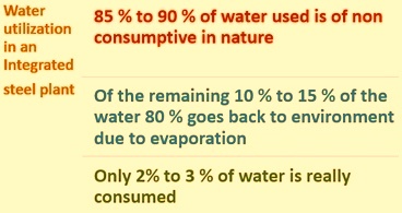
Fig 1 Water utilization in an integrated steel plant
The water finally consumed in an integrated steel plant is normally in the range of around 4 cum to 5 cum per ton of crude steel. Hence under this scenario of water usage in the integrated steel plant, it is necessary to define the terms ‘reuse’ and ‘recycling’ of water in a more precise way. While the term ‘reuse’ indicates that water is used and then returned to water body for subsequent use by any other consumer, the term ‘recycling’ implies repeated use of water for the same or successive processes. In case the water body to which the used water is retuned happens to be sea then there is a direct loss of the water resource. The usage of water has undergone a further change in recent years and today the integrated steel plants are aiming at total recycling and zero discharge.
Use of water by the processes of the steel plant
Depending on the facilities, the layout, discharge limitations, and available water supplies, the usage of water varies widely in integrated steel plants. Some of the specific usage of water are described below.
Cooling water
Cooling water has the largest application and constitutes maximum in the usage of water in the steel plant. In addition to the classification by direct cooling (contact) and indirect cooling (non-contact) water criteria, cooling systems water use can be generalized in the following types.
In once-through systems, water is used once prior to its discharge, as in the cooling of condensers, furnace components, and other miscellaneous applications. This mode of cooling is typically in indirect cooling applications where the water is intentionally restricted from coming into contact with the processing material or other main process or resultant process streams originating from the production shops, such as exhaust gas, liquid fluids, etc. This approach is more prevalent in the plants which are located adjacent to large water bodies, rivers, and lakes etc. where water is available in abundant quantities.
In evaporative recirculating systems, both direct and indirect cooling applications utilize principal of evaporation. In these systems, the heat absorbed by the water from a process is easily transferred to the environment (air) by exposing the water to the atmosphere. This evaporation reduces the bulk water temperature, enabling the water to be reused. This cooling method is normally used in evaporative cooling towers, and to a lesser extent, in lagoons and spray ponds.
In indirect water cooling systems, the limit to which water can be recycled in this manner is dependent on the water quality requirements of the process being cooled, the raw water quality, and ambient air temperature. As the water is evaporated, the minerals and other constituents for the most part remain in the water and become concentrated. This concentration mechanism increases the total dissolved solids (TDS) in the system and, if not compensated, may lead to water-related problems. Generally, the TDS concentration in the system is controlled by bleeding off some of the water from the system (blow down).
This is also true for the direct water cooling systems, and attention is normally given to the constituents originating from the process. These systems frequently require some treatment for the removal of solids, oil, etc. prior to cooling and recycle.
In both direct and indirect water cooling systems, the possible amount of water recycle is highly dependent on the water quality requirements and constraints of the systems being cooled. Because of this, some discharge blow down is required from these systems to maintain the desired water quality. The balance for an evaporative water system is dictated by the following interrelationship between makeup water, evaporation loss, and blow down water. The blow down water in this equation includes uncontrolled losses such as tower drift, windage losses, exhaust entrainment, spillage, and leakage etc.
Makeup water (MU) = Evaporation loss (EV) + Blow down water (BD)
Cycles of concentration and concentration ratio are terms used to indicate the degree of concentration of the recirculating water as compared to that of the makeup water. The degree of concentration is dictated by the relationship of makeup water to blow down water, given that evaporation (heat load) is constant over time. The evaporating water is pure water vapour, leaving behind soluble water impurities that can be measured. Analytically, measurement of these dissolved minerals in the makeup water and blow down water can also indicate this concentration (Conc.) phenomenon as shown below.
Concentration ratio (CR) = MU (cum per min.)/BD (cum per min.) = Conc. (BD)/Conc. (MU)
An accepted thumb rule to estimate evaporation in a recirculating system is that for every 10 deg C temperature drop across the evaporative process, around 1. 65 % of the recirculating water is lost due to evaporation.
This thumb rule can have variation depending on the location of the plant. In areas of high humidity, evaporative loss may be as low as 1.25 %, while in dry areas it can be as high as 2.0 %. Similar variations can also be due to the seasonal effects. A second method to determine makeup (MU) water is as follows:
MU = EV x (CR/CR-1)
In direct cooling systems, when water is applied to hot steel in the process, analytical measurement of dissolved salts may provide a skewed picture. Some of the mineral content may precipitate out on the hot surface of steel in process as the water evaporates. Conversely, soluble elements from the process may also dissolve in the water, increasing their level, as in the gas cleaning applications of water
The closed (non-evaporative) recirculating systems usually incorporate the use of a heat exchanger mechanism where the heat of the recirculated water system is transferred to a second water system or to the air through conductive cooling. This transfer of heat is done through water/water heat exchangers of plate and frame or shell and tube design, or through air coolers of wet surface or dry design. The same cooling water is used in a continuous cycle with little or no water loss. Usually associated with higher water quality applications, these systems are typically not exposed directly to the environment and do not have a concentration mechanism. As a general example, the radiator cooling system of an automobile is an example of a closed loop cooling system.
Majority of once-through systems are limited to non-contact or indirect cooling applications. Earlier contact or direct cooling applications were used to be of the once through design, but these mostly have been converted to recirculating systems, incorporating primarily evaporative cooling towers to meet discharge requirements. Most closed (non-evaporative) systems are being used to cool process equipments which generally require higher quality water in terms of hardness, suspended solids, and dissolved solids. Sometimes these requirements need pre-treatment of the water to meet the desired characteristics.
For the purpose of the conservation of water, some steel plants use cascading water systems, whereby water is intentionally transferred from one system to another. A common example is the use of the blow down water from an indirect water cooling system as makeup to a direct water cooling system. The reverse of this is rarely employed without additional treatment because the direct cooling waters can contain potentially troublesome constituents originated from the process. Because of constituent levels in direct cooling water, the use of indirect cooling water is preferred in heat exchange equipment, wherever practical and feasible. In some applications, boiler feed water is also used.
Usage of water and generation of waste water in the processes of steel plant
The following is a brief outline of the usage of water and generation of waste water in the processes of the steel plant.
Coke oven and by product plant
The water used in coke oven and by product plant is mostly for indirect cooling in a variety of cooling and condensing operations. Moisture of the coking coal used for coke production and the condensation of the process steam makes the by-product process a net generator of process water. Sources of process waste water include (i) excess ammonia liquor from the primary cooler tar decanter, and (ii) atmospheric condenser waste water from the crystallizer, the final coolers, light oil recovery operations, desulfurization processes, and air pollution control operations. Most of the waste water generated at the coke oven and by product plant is due to the moisture in the coking coal and steam condensation. Additional sources of waste water may include condensates from drip pots and gas lines.
The largest consumption of water in coke oven plant is because of the wet quenching of the hot coke. The amount of water required for hot coke quenching can vary and has been reported to be from 0.4 cum/ton to 3.0 cum/ton of coke. Necessary quantity of water is needed to cool the hot coke, yet leave enough heat in the coke to evaporate any entrained water. Some steel plants use untreated process waste water for coke wet quenching, while others use treated process waters or service waters. In some of the plants, there is a requirement to control the level of TDS in the quench water because of potential fears for air pollution. This requirement has affected the use of untreated process waste water for coke wet quenching in these plants.
Sinter plant
The principal usage of water in a sinter plant is for controlling the moisture content of the pre-sinter mix, for dust control, and for sinter product cooling. Some indirect cooling of equipment is also involved. For emissions control in sinter plants, either electrostatic precipitator (ESP) or wet venturi-type scrubber technology is typically employed for dust control. In ESP applications, some water is sometimes added to control exhaust temperature and to condition the particulate prior to capture.
In sinter plants with scrubber systems, water is sprayed into the gas stream to capture the emissions from the sinter operation to meet stack emissions requirements. The associated water system typically includes clarifying thickeners, a cooling tower, and the adjustment of pH.
Blast furnace
The blast furnace is one of the largest water users in the operation of the steel plant. The primary water use is for indirect cooling of various parts of the furnace and auxiliaries, including the tuyeres, hearth staves, bosh and stack cooling plates and staves, slag notch (if it is there), and stove valves. The earlier approach has been to use once-through cooling water, but in these days the blast furnaces have incorporated cooling systems along with closed-loop water systems for hot blast valves, tuyeres, and staves. Additionally, water is also used for furnace moisture injection (steam), dust control, and slag granulation.
Direct cooling of water is primarily associated with blast-furnace gas cleaning operations necessary to recover the fuel value of the BF top off gas. In venturi-type scrubbers and spray-cooled gas coolers, water contacts the gas, cleans and cools it for reuse. This water system usually consists of thickeners, dewatering devices, and evaporative cooling towers. Chemical treatment usually consists of settling supports, pH adjustment, and inhibitors, depending on the nature of the particulate and gas leaving the furnace. As the amount of water recycling increases in these systems, the control of TDS and the increased concentration of specifically monitored elements or compounds become concerns.
Treatment for the reduction of TDS is dependent upon the parameters of concern and can involve more sophisticated treatment systems. Typically, the blast-furnace process waters contain ammonia, phenols, cyanide, lead, and zinc. Additional treatment for these parameters may be required prior to discharge of any blow down from the recycle system. In many facilities, a significant portion of the recirculated water can be consumed rather than discharged by utilizing it for slag granulation.
Basic oxygen furnace (BOF) steel making
The BOF steel making process has extensive usage of water. Indirect cooling is used for the oxygen lance, trunnion, converter hood, and ductwork. Both closed loop and evaporative systems are established methods for handling the cooling requirements for these components. The trend for hood cooling in recent years has been toward the closed-loop cooling approach to extend hood life. Some BOF hoods have evaporative cooling system, with water requirements similar to those of high pressure boiler applications.
Gas handling for the various basic oxygen processes can be categorized as either open combustion or suppressed combustion hood systems. In full combustion systems, excess air is allowed to enter the exhaust stream in the hood which enables the oxygen blow to accomplish a complete reaction, converting CO to CO2. In suppressed combustion systems, the hood is with skirt to prevent excess air from entering the exhaust. Normally, the amount of particulate emissions generated by either method equals 1 % to 3 % of the steel production. The suppressed combustion system is more popular these days because the particulate generated is usually larger, the temperatures generated in the hood are generally lower, and there is lower volume of gas to be handled. This reduces the size of the equipment required to convey and clean the gas.
In either full or suppressed combustion gas cleaning systems, water is used for initial cooling of the gas in the ductwork and/or in a quencher to reduce gas temperature and volume. Full combustion gas cleaning systems use either electrostatic precipitator (semi-wet) or venturi scrubber (wet) technology. After initial conditioning in a precipitator-based system, little or no water is used because the captured dust is handled on a dry basis. Precipitators are generally not used on suppressed combustion systems because the potential for explosion exists due to the presence of CO gas.
The scrubber-based system usually incorporates separate quencher and venturi-type scrubbers for gas cooling and cleaning purposes. The auxiliary water systems normally consist of a clarifying thickener and dewatering devices for the solids captured. Upon leaving the thickener, the cleaned water is returned to the venturi, typically without cooling. After the venturi scrubber, the venturi effluent is typically reused as supply to the quencher.
Because of the lime carryover in the exhaust gas, the high gas temperature, and the fine particulate nature of the dust evolved, water-related problems, including mineral precipitation and fouling, may interfere with scrubber operations. Problems include plugging of the venturi nozzles and fouling in the venturi/quencher throats. Different water quality treatment approaches have been used which include pH/alkalinity control, solids management, and use of inhibitor.
Ladle furnace
In the ladle furnace (LF) indirect cooling water is used to cool the roof, clamps, arms, cables, and associated equipment. Cooling is typically via an open recirculating system.
Vacuum degassing unit
Water usage is primarily associated with the vacuum generating/gas cleaning system. The vacuum is generated by injecting steam through multi-point ejectors leading to an atmospheric condenser. As the steel exhaust emissions are drawn in contact with the steam, the particulate is wetted and collects in the condenser water. The water system normally consists of a cooling tower, solids settling, and solids removal facilities.
Continuous casting machines
Water use and quality are critical to the success of continuous casting (CC) operations. Water use in the CC machines is categorized by function in the CC process namely (i) primary (mould) cooling, (ii) secondary (spray) cooling, and (iii) auxiliary (equipment) cooling.
Water management practices in CCM has evolved along with the development of CC technology and the demands for equipment reliability and quality grew with the development of the CC technology. A significant improvement had been made when the mould cooling water circuit was isolated as a closed indirect cooling water system. This has virtually eliminated process contamination and mineral scaling as the cause for mould related failures. Further improvements have been made when direct cooling and indirect cooling requirements were separated into separate water systems.
The primary cooling process consist of the indirect cooling of the liquid steel in the mould to its semi-finished form by passing high quality water through a highly conductive copper mould. Closed-loop non-evaporative cooling is mainly used since high surface and strand quality are required. Because of the high heat flux encountered in the mould, pre-treatment is normally carried out for removal of scale-forming constituents.
Secondary or spray cooling occurs as the strand leaves the mould, with contact water sprays covering the surface of the strand. Spray cooling allows for the extraction of heat as it travels from the liquid core to the surface until solidification is complete. This contact water system normally incorporate settling tanks (scale pits), oil skimmers, straining devices, and deep bed filtration equipment since low suspended solids levels are to be maintained. Water treatment includes possibility of contamination from grease, hydraulic fluids, and mould lubricants that usually get collected and concentrated in the system.
Auxiliary cooling is indirect or internal cooling of the CC equipment. Applications typically include heat exchangers, internal roll cooling, frames, bearings, compressors, exposed instrumentation, and other miscellaneous components. Evaporative cooling systems are prevalent for these applications. Electromagnetic stirring devices and high temperature exposed components such as centre bearings usually require the installation of closed-loop cooling systems, which may require high-quality water.
Cascading water systems are not unusual in CC water systems as water quality requirements are typically less stringent for direct cooling systems than for indirect cooling systems.
Hot rolling mills
After continuous casting, the cast steel product is transferred to a reheating furnace to bring the semi-finished steel to a uniform temperature. Whether the reheating furnace is of skid, walking beam, or tunnel design, indirect cooling water is typically used to provide the cooling for doors, internally cooled rolls, skid pipes, beams, bearings, and miscellaneous equipment.
In the hot rolling mill, the mill stand work rolls are cooled by a direct water cooling system to maintain roll contour, to prevent surface cracking of the steel rolls due to sudden temperature changes, to minimize fire checking, and to extend roll life. Water is also used in descalar in the form of high pressure jets to remove scale from the reheated steel before rolling to maintain surface quality. It is also used between certain roll stands to maintain surface cleanliness of the steel in process. In addition, water is used as flume flushing to transport the scale to the scale pits for removal.
The rolling mill water system typically incorporates scale pits, oil skimmers, straining devices, solids removal with clarifiers and/or deep bed filtration equipment (when low suspended solids levels are to be maintained), and cooling towers. Waste water treatment usually includes facilities for likely contamination from fine mill scale, grease, hydraulic fluids, and rolling oils which gets collected in this system. The water system for the heat treatment facilities is usually separated from the rolling mill, with separate settling, cooling, straining, and water filtration facilities.
Cold rolling mills and coating facilities
The cold rolling mills and coating facilities include pickling lines, cold reduction mill, annealing, tempering mill, cleaning lines, and coating lines (tin, galvanized, terne, etc.), water is used primarily as indirect cooling water, solution make up, and rinsing water. Indirect cooling water facilities usually incorporates cooling towers, while some equipment may include closed-loop systems to meet specific high purity water quality requirements. Usual process waste waters from these operations include rinses and spent concentrates from alkaline cleaners, pickling solutions, plating solutions, and electrochemical treating solutions. Many technologies are being utilized to recycle and/or reuse the concentrated solutions. However, the rinse waters require treatment to meet discharge requirements.
In treatment of these waste waters, attention is normally given to (i) the type of plating solutions, cleaners, and pickling solutions utilized, (ii) oil and grease, (iii) dissolved metals, (iv) organic compounds, and (v) lubricants that may be present in the waste water.

Leave a Comment