Induction Furnace and Important Operational Aspects
Induction Furnace and Important Operational Aspects
The development of the induction furnace for steel making has been a boon to the small steel producers. These furnaces are easy to install, operate and maintain. These furnaces are smaller in heat size with a low cost investment and preferred by lower capacity steel plants. In these furnaces, steel is produced by melting the charge material using the heat produced by electromagnetic field.
The induction furnace consists basically of a crucible, inductor coil, and shell, cooling system and tilting mechanism. The crucible is formed from refractory material, which the furnace coils is lined with. This crucible holds the charge material and subsequently the melt. The choice of refractory material depends on the type of the charge and basically consist of either acidic, basic or neutral refractories.
The inductor coil is a tubular copper coil with specific number of turns. An alternating current (AC) passes through it and magnetic flux is generated within the conductor. The magnetic flux generated induces eddy currents that enable the heating and subsequently the melting process in the crucible.
The shell is the outer part of the furnace. This houses the crucible and the inductor coils, and has higher thermal capacity. It is made of rectangular parallelepiped with low carbon steel plate and joined at the corners by edge carriers from angular pieces and strips of non-magnetic metal.
The cooling system is normally a through one way flow system with the tubular copper coils connected to water source through flexible rubber hoses. The cooling process is important because the circuit of the furnace appears resistive, and the real power is not only consumed in the charged material but also in the resistance of the coil. This coil loss as well as the loss of heat conducted from the charge through the refractory crucible requires the coil to be cooled with water as the cooling medium to prevent undue temperature rise of the copper coils.
Raw materials and energy source
Steel melting scrap, direct reduced iron and pig iron/cast irons are the input raw materials for an induction furnace. The ratio of these items and the technology of melting these input materials varies according to the availability of raw materials and location of the plant. Further selected raw materials is required for the production of specific quality steel. For better and efficient operation of melting in induction furnace, raw material charge must fulfill the following criteria.
- It must be as dense as possible. Compaction of scrap is important for ensuring uniform and rapid heating as well as for energy saving.
- It must be clean. Rust, oil, grease, and sand etc. should preferably be nil.
- It must be metallurgically clean, i.e. free from slag lumps, oxides etc., particularly for direct reduced iron, skull and ferro alloys.
- There are no or less sharp pointed edges, particularly in case of heavy and bulky scrap.
- It must be segregated from harmful ingredients like explosives, closed containers, evaporative substances and readily available in chargeable sizes on the shop floor.
Electricity is the only energy source for steel melting in the induction furnace. Induction furnace is to run at maximum power since beginning. There are some misconception of running furnace at low tap initially and then gradually increase to higher tap. Maximum power input increases rate of melting and hence reduces cycle time of a heat. Power factor to be maintained near to one.
Drop of voltage from the source also to be monitored for better energy efficiency. Further power consumption rate is dependent on the furnace size and it is lowered as the furnace capacity is increased approximately up to 15 to 17 tons and thereafter consumption rate remains almost constant at around 600 kWh/ton.
Important aspects of operation
As liquid steel is excited by current opposite to current flowing in induction coil, it is agitated to raise its surface in the center. Surface of liquid steel is risen higher as frequency becomes lower, i.e. agitation of the liquid steel occurs stronger in low-frequency furnace than in high-frequency furnace. This effect of agitation makes it possible to ensure uniform temperature of the liquid steel and its uniform quality as well as to promote entrapment of material charged and fusion of chemical composition adjusting agents, specially carbon addition. On the other hand, excessive agitation may cause such troubles as oxidative wearing of liquid steel and fusing out of refractories or danger of spattering of liquid steel.
Once the melting is complete, the slag is skimmed off. Slag generated during melting has tendency to stick on the furnace wall. This reduces volume of furnace hence reduces metal output per heat. Superheating of metal is done at higher temperature and held for few minutes. This inhibits slag to deposit on the furnace lining keeping furnace clean with full volume.
The composition of the slag varies depending on the specific process being used and the type of steel being produced. The compositions of furnace and ladle slags are often very complex. The slag which is formed is the result of complex reactions between silica, iron oxide from steel scrap, other oxidation by products from melting, and reactions with refractory linings. The slag consists of a complex liquid phase of oxides of iron, manganese, magnesium and silicon, silicates and sulfides plus a host of other compounds, which may include alumina, calcium oxides and sulfides, rare earth oxides and sulfides etc.
While producing the steel, the chemistry of end product is controlled. The chemical analysis of all the input materials is done to have a decision on the charge mix. After completing 50 % charging of the input materials, a bath sample is analyzed for chemical composition. Based on the chemical analysis of the bath sample at this stage calculations are made for further additions of the metallics. If the bath sample at this stage shows high percentage of carbon, sulphur and phosphorus then the direct reduced iron content of the charge is increased. Final bath sample is taken when 80 % melting is completed. Based on the analysis of this sample, another adjustment is made in the charge. The lower content of carbon in the sample is corrected by increasing the quantity of pig iron/cast iron in the charge. Silicon and manganese in the metal is oxidized by the iron oxide of the direct reduced iron. Sulphur is also diluted by the direct reduced iron. Because of use of direct reduced iron the trace elements in the steel made in the induction furnace remains under control.
The liquid steel is the desired output of the induction furnace. The quantity depends upon the capacity of the furnace, and the quality depends upon the raw materials and the steel composition. The tapping temperature depends upon the type of steel and the super heat needed in the liquid steel for its end use. Tapping of steel at high temperatures increases refractory erosion and power consumption.
Unnecessary superheating of liquid steel to high temperature costs to energy significantly. Minimizing the overheating of molten bath saves energy. Depending on steel specification and temperature loss during transfer of liquid steel to continuous casting machine, superheat temperature is to be decided. In every heat, temperature of the liquid steel bath is to be measured and monitored to get optimum energy saving. Proper power control systems with potentiometer adjustment need to be provided for minimizing energy losses due to overheating.
Tilting of the furnace is to effect pouring of the melt is a last operational activity before casting. The furnace is usually tilted to achieve an angle of 90 degree or greater for complete pouring of the liquid steel.
Other aspects of induction furnace steel making
Depending on the installed power density and the melting practice, the thermal efficiency of the induction furnace can exceed 80 %, but usually it is in the range of 60 % to 78 %.
Induction furnaces are normally kept open during the entire melting process where the workers engage in slag skimming and monitoring of the quality of molten bath. However, this leads to significant heat loss and hence special covers or lids need to be installed for reducing heat losses. In particular, reducing the time the lid is kept open while melting, can lead to substantial energy savings.
The theoretical requirement of energy for melting iron is only 340 kWh per ton whereas the actual power required is around 600 kWh. This difference is due to two factors namely (i) inherent in the principle of melting in an induction furnace which include the inefficiency in electrical bus bar losses, eddy current losses, refractory losses, and cooling water losses etc., and (ii) the operational losses which are largely due to unnecessary and excessive holding of liquid steel in the induction furnace.
Induction furnace equipment should be placed with minimum distance between each equipment to reduce wiring losses. To reduce the wiring losses remarkably, it is essential to shorten the distance between furnace body and power factor improving capacitor as very large current flows between them.
Efficiency of induction furnace is expressed as a total, deducting electrical and heat transfer losses. Typical heat balance diagram of high and medium frequency crucible type induction furnace is shown in Fig. 1. Electrical losses consist in transformer, frequency converter, condenser, wiring, cable, coil, etc. Loss in coil is essential factor, on which the furnace capacity depends. Heat losses in induction furnace consist of conduction loss of heat escaping from furnace wall to coil side, radiation loss of heat released from melt surface, absorption loss in ring hood, slag melting loss, etc. The coils of furnace are water cooled which also results in heat loss. Heat efficiency of high and medium frequency furnaces (60 % – 78 %) is slightly larger than that of low frequency furnace (58 % – 71 %).
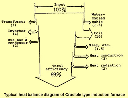
Fig 1 Typical heat balance diagram of crucible induction furnace
One of the most critical problems with the induction furnace steel making process is its limitation to refine steel to reduce phosphorous content below the desired limits. Higher phosphorous and pick up of nitrogen during induction melting make the final product hard and brittle and unusable for many critical applications. Besides, the quality of sponge iron, which is sourced mostly from coal based production units, is also of poor quality, particularly in terms of metallization and phosphorus content. Because of these drawbacks, higher use of DRI in the induction furnace results in low yield and higher energy/power consumption as well as higher phosphorous in the steel.
Environmental emissions
Since no coal or fuel is burned in the induction furnace and no refining procedures are executed, the emissions solely depend on the cleanliness and the composition of the charged material. Two major categories of emissions can be distinguished. The first, and major, category relates to the charge cleanliness, e.g. rust, dirt, foundry sand, paint, oil, galvanized or soldered metal, all of which are elements which give rise to the emission of dust and fumes (organic or metallic). The second category relates to chemical reactions at high temperatures, (e.g. while holding or adjusting the metal composition), which can give rise to metallurgical fume due to oxidation.
Additionally the refractory lining (acidic-SiO2, neutral-Al2O3, or basic-MgO) may add a small amount of dust particles to the emission. It is difficult to obtain average emission data since the charge cleanliness, which is the dominant contributor to emissions, varies from unit to unit to a great extent.
Emission rate from an induction furnace depends upon the charge material which again depends upon the product being made from that furnace. If the product being made is a good quality casting then emissions are of the order of 1 to 2 kg/ton metal charge but if it is ingot/billet which then emission rates of the order of 10 to 20 kg/ton metal charge are normal. The highest emission rates occur during charging and at the beginning of the melting cycle. Particle sizes range from 1 – 100 micro meter, with more than 50 % being smaller than 10 -20 micro meter. Charging oily scrap or borings in a cold furnace leads to the presence of organic vapours in the exhaust gases.
Huge amounts of hot fumes and gases are released from the open furnace vessels during induction furnace operations and spread across the shop floor, affecting the health of the workers.
As regards the pollution potential of the induction furnaces, it may be observed that volume, quantity and harmful emission of solid and gaseous contaminants are fairly low as compared to electric arc furnace. The equipment need not be as elaborate as electric arc furnace so as to make it cost effective for small scale induction furnace units. At the same time, the pollutants emitted should be in conformity to regulations.
The steps involved for pollution control include capturing of fumes by a properly designed suction hood mechanism. The hood should draw the entire exhaust gases which should be cleaned by cyclone separator. Further cleaning of finer particulates is carried out either through a bag filter or in wet scrubber, and then letting out clean gases to pass into the atmosphere. The suction hood mechanism could be side, swivel or canopy hood type. The last step is disposal of solid matter left as sludge or dust.
The concentration of particulates in the emission from an induction furnace for the production of liquid steel should not exceed 100 mg/cum, expressed at reference conditions of 0 deg C, 101.325 kPa and dry conditions without correction for oxygen content, and compensated for any effect of dilution air to the concentration.
Safety and induction furnaces
Working with molten metal has always been a dangerous job. Present day high efficiency induction furnaces have improved working conditions by making melt shops cooler, cleaner and generally less hostile work places since the heat noise and fumes associated with the combustion furnaces are not there. However these furnaces have not eliminated the dangers inherent in working close to liquid metal.
Reasons of most accidents in the melt shops with induction furnaces are (i) the introduction of wet or damp metal in the melt, causing a water/metal explosion, (ii) lack of operator skills during temperature taking, sampling or the additions of ferro alloys, causing metal splash, (iii) dropping of large pieces of charge material into the molten bath, causing metal splash, (iv) improper attention to charging causing bridging action, (v) failure to stand behind safety lines, causing a trapping situation, (vi) coming into contact with electrical conductors, overriding safety interlock switches or coming into contact with incompletely discharged capacitors, causing electric shocks or electrocution, and (vii) lack of proper operator training.

Comments on Post (1)
B Raha
How to use inferior quality scrap in induction furnace for making good quality steel and how to undertake properly addition of synthetic slag in Induction furnace.