Continuous casting of steel billets
Continuous casting of steel billets
Continuous casting of steel is a process in which liquid steel is continuously solidified into a strand of metal. Depending on the dimensions of the strand, these semi-finished products are called slabs, blooms or billets. Steel billet has a square cross section with one side normally 150 mm or less. It is a feed material for rolling of steel in light section mills, bar mills, and wire rod mills. Steel billets are also used in forging of certain products.
The process of continuous casting was invented in the 1950s in an attempt to increase the productivity of steel production. Previously only ingot casting was available which still has its benefits and advantages but does not always meet the productivity demands. Since then, continuous casting has been developed further to improve on yield, quality and cost efficiency.
Continuous casting of steel is now the method of choice by all steel producers replacing the old method of ingot casting. Distinguished by its many advantages, this process has gone through many improvements and was and still is the subject of wide range of studies both empirically and mathematically. Continuous casting of steel billets is one of the type of continuous casting adopted in steel industry, by which, steel billets are produced continuously and simultaneously. This type of process requires great control of operating parameters in order to produce sound and continuous billets. The process can be divided into a number of steps starting by pouring the hot liquid steel from the steelmaking furnace into the ladle, where the steel chemistry is being adjusted in secondary steelmaking, then pouring into the distributor (tundish), and from the distributor into the casting mould. Solidification of steel begins in the copper casting mould by indirect cooling, an area which was subjected to many studies. From mould the cast billet undergoes secondary cooling with water sprays.
The steel billet production got a boost in the 1960s since at this time the mini-mill concept was evolved by combining electric steel making with the continuous casting and a lean organizational structure to produce a profitable new culture of steel production. The billet producers though highly profitable lagged in the production of high quality continuously cast products.
A survey conducted in1980s has shown that mould design and the operation of continuous casting of billets were not standardized and each company was doing something different. Brimacombe and coworkers in the late 1970s began to explore the inner working of the billet mould and established the links between the mould designs, the operation parameters, and the billet quality with the aid of mathematical models and in-plant measurements. Because of these efforts, billet casting moved towards standard designs and operating parameters resulting into substantial improvement in the cast billet quality. This was revealed by a new survey conducted in 1994 and it was noticed that the billet producers had started supplying special bar quality billets to the automotive sector successfully by meeting stringent quality requirements. Since that time, billet casting machine suppliers have re-examined the casting speeds for the continuous casting of the billets, giving rise to a number of new developments aimed at the higher productivity. A common feature of high speed casting technology for the billets is the increase in the mould length.
A very wide range of billet continuous casting machines are now available. These machines have different bending radiuses, are of single strand to eight strands and have casting speeds up to 6 m/minute. A single strand billet caster with 6 m radius is shown in Fig 1 while two eight stands billet casting machines are shown in Fig 2.
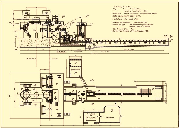
Fig 1 Single strand billet caster
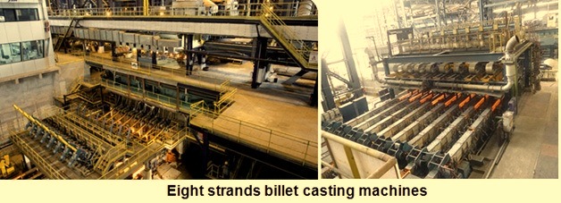
Fig 2 Eight strand billet casting machines
The process of the continuous casting of steel billets is described below.
Steel ladle
Liquid steel is transferred from steelmaking facilities to the billet casting machine in the steel ladle. During this transfer there are opportunities available for the control of cleanliness, composition and temperature of the liquid steel. If these opportunities are not availed then the liquid steel delivered to the billet casting machine is dirty and either too hot or too cold. Casting of quality billets is then a much more difficult task.
During the transfer of liquid steel to the billet caster, a major problem is the oxygen (O2) absorption from the air, furnace slag, and the ladle refractory lining. It is necessary to minimize O2 pick up during each transfer step. Slag overflow in the steel ladle is to be prevented from the steelmaking furnace at the end of the tapping. The surface of the steel in the ladle is needed to be covered with a synthetic slag (i) for preventing O2 absorption from the air, (ii) for the absorption of non-metallic inclusions, and (iii) for the minimization of the heat loss. In some plants, steel ladle is covered at the top with a ladle cover. Further during casting, the steel ladle is equipped with a refractory tube to prevent O2 pick up as the steel is poured into the tundish. Flow of steel from the ladle to the tundish is controlled with a slide gate valve. In some plants the weight of the steel ladle is continuously measured with the help of load cells.
Normally rinsing of the liquid steel with the inert argon (Ar) gas is carried out to homogenize the temperature of steel. The temperature control of the liquid steel is important for controlling the cast structure as well as for the prevention of the operating problems such as formation of skull in ladle and tundish, break-outs etc. The flow rate and duration of Ar rinsing need to be controlled since the gas discharging from the steel brings it into contact with air unless special measures are taken.
Tundish
Tundish has to play many roles during the continuous casting of the steel billets. It acts as a distributor, discharging steel to the several strands of the billet casting machine. It also facilitates the control of the flow of the liquid steel into the mould since it has a constant and lower hydrostatic head than the steel ladle. This is important mainly during the start-up of the caster, since the tundish can be filled with steel to its normal steady-state level before starting the pouring of the liquid steel in the mould. The other important phenomenon which can take place in the tundish is the floating of inclusions which helps in the cleanliness of the cast product. Further the tundish can also be used as a reactor as well, for the addition of agents such s calcium (Ca), for inclusion morphology control.
Because of the above functions, the shape and the size of the tundish are dictated mainly by the need of controlling the fluid flow. Since the heat size, dimensions of the cast billet, number of strands, strand spacing, and pouring rate differ from one plant to another plant; a unique optimum tundish design does not exist. However the following are the key features of a well-designed tundish.
- The tundish design is to maximize the float-out of the inclusions. For this tundish volume is to be large, although other mitigating factors limit its size. As an example, if heats having different composition are to be cast in sequence, without interruption of the casting operation, the volume of the ‘mixed’ steel in the tundish must be minimized since the mixed steel is off grade and can represent a yield loss.
- The residence time of steel flowing to the each of the strands must be the same for ensuring the quality of the quality of the steel.
- The short circuiting of steel through the tundish is to be minimal, i.e., to the extent possible, plug flow is to be achieved.
- The flow pattern in the tundish is to permit much of the steel to move close to the surface where inclusion floating out can be absorbed by the tundish slag. This is important since the distance the inclusions can travel by buoyancy alone is small in the time available in the tundish.
- Dead volume is to be minimized since it effectively reduces the residence time of the steel.
- Turbulence from the incoming ladle stream need to be isolated, particularly when open stream pouring from tundish to the mould. The turbulence influences the roughness of the tundish stream and the entrainment of gas in the mould pool.
- The depth of the tundish is to be sufficient, in excess of about 500 mm, to prevent vortexing at the nozzle wells, which can draw the slag lower down in the mould pool.
Determination of an optimum tundish design needs the specifications of shape, dimensions and the location and size of internal flow control devices such as dams and weirs. These are normally achieved by the extensive use of the water models and/or mathematical models.
One more aspect of the tundish design which influences productivity and quality is the prevention of the re-oxidation of the liquid steel. Thus a covering slag with a capacity of inclusion absorption is applied to prevent O2 absorption from the air. The steel flowing from the tundish to the mould is further protected by passing it through a refractory tube or an inert gas shroud. The latter is used when casting small section billets where the mould cavity is too small to accommodate a refractory tube. For the casting of the lower quality billets, the steel usually is poured through the air without concern for re-oxidation. The tundish is lined with a refractory which is to be inert to the steel. Also the de-oxidants in the steel such as Ca or aluminum (Al), for instance, must not react with the oxides comprising the refractory lining. In some plants, the tundish is preheated to drive out the volatile constituents in the certain type of the linings, which may contribute hydrogen to the steel, and also for the better control of the steel temperature.
A major problem with tundish operation is the clogging of the pouring nozzles by solid inclusions such as alumina (Al2O3). Even though the inclusions are small compared with the diameter of the nozzle, they usually adhere to the refractory via the boundary layer and eventually, by successive build-up, form a bridge across the nozzle choking off the flow. The problem is severe for the casting of small billets, which require smaller diameter nozzles. When casting bigger sections using larger nozzles, Ar is often flushed continuously through the nozzle to prevent excessive build-up. Nozzle clogging is not a problem if the inclusions are in the liquid state. Hence for the trouble free casting of the Al killed steels into the billets, Ca is added in the correct amount to yield calcium aluminate inclusions.
Pouring rate through the tundish nozzle is accomplished by different techniques depending on the section size being cast. For larger sections, employing a refractory tube between the tundish and mould, a stopper rod or a slide gate valve is normally used to control the flow, automatic flow control to achieve a constant meniscus level and casting speed is normally used. In case of smaller section billets, with open stream pouring, there is usually no flow control on the tundish. The flow rate is then adjusted by the selection of the appropriate nozzle diameter and maintenance of specific steel hydrostatic head in the tundish. Meniscus level control is then obtained by varying the casting speed. Maintenance of the liquid steel head in the tundish is carried out either manually or by continuous weighing the tundish with load cell and connecting the signal to the slide gate valve on the ladle.
The normal time needed to cast a heat of the liquid steel is around one hour, which is to be matched to the time of 30 to 40 minutes up to two hours needed for the supply of heat to the billet casting machine.
Mould
The mould is the ‘heart’ of the casting machine. It is also the primary device for the heat removal. The functions of the mould are (i) to remove superheat from the liquid steel, (ii) to grow a solid shell of sufficient thickness, (iii) to contain the liquid pool below the mould without break-outs, and (iv) to support the shell in its initial growth. Since the mould governs the heat removal, the design and the operation of the mould greatly affects internal and the surface quality of the cast billets. Freedom from surface cracks is very important especially if the cast billets are to be hot charged in the reheating furnace for rolling since surface cracks oxidize and form defect of oxide seams during rolling.
The mould may be straight or may have a curvature of 4 m to 15 m in radius. Curved moulds are used with curve strands to reduce the height of the casting machine and the capital cost. Straight moulds help in the inclusion distribution in the cast product. In case of the curved mould, inclusion floating can be trapped preferentially by the solidification front adjacent to the inside radius face to form a band. Since this does not happen in the straight mould, the inclusions are more evenly distributed. The extent to which this concern is valid depends on the cleanliness of the steel entering the mould and the quality requirements needed for the cast billets. In any case, cast steel leaving a straight mould is generally bent gradually to a horizontal orientation to reduce the caster height. However, in some plants, the moulds and the sub-mould region are straight so that the cast product is not subjected to mechanical bending forces that may generate cracks. With a curved mould, the steel strands need to be straightened to a horizontal position prior to being cut into lengths.
Regardless of whether moulds are straight or curved, the basic designs of the moulds are the same. Tube moulds are used for the continuous casting of the steel billets. These moulds consist of copper (Cu) tube positioned concentrically inside a steel baffle with cooling water flowing through the annulus between the two. The wall thickness of the Cu tube ranges from about 6 mm to 20 mm. The thicker wall tube moulds are used for the larger sections. Mould tubes are fabricated from different grades of Cu alloys. Cu alloys containing phosphorus, silver (silver bearing), or chromium and zirconium are commonly used materials for the mould tubes.
During the casting, the mould is lubricated and reciprocated to prevent the steel from sticking to the Cu, which would result in rupture of the solid skin. The oscillating mould generally follow a sinusoidal wave form, the frequecy and amplitude of which are adjusted to ensure that for a fraction of a second during the down stroke, the mould is moving more rapidly than the descending strand. This period of ‘negative strip’ has been found to influence the formation of oscillation marks on the surface of the strand. The lubricants employed normally depend on the section size being cast.
In case of small sections such as 100 mm square billets, in which steel is poued in an open stream from the tundish to the mould, rapeseed oil or synthetic oil is used. The oil is pumped to an oiling plate at the top of the mould from which it seeps down the inside of the mould wall. The precise lubrication action of the oil, which pyrolyzes in contact with the liquid steel, is not very clear. When casting larger sections, the steel is introduced into the mould through submerged entry nozzle. In this case, the lubrication is done by adding casting powder to the meniscus, where it contact the steel, melts, and drawn into the gap between the solidifying shell and the oscillating mould. The composition of the powder consisting typically of oxides, carbon and calcium fluoride, is adjusted to control its melting range and viscosity. Depending also on composition are the thermal conductivity, and thickness of the mould powder layer in the mould/steel gap, which influence the rate of heat extraction by the mould.
A variety of oils such as vegetable, synthetic and blends can be used. Although the flash point of the oils is a key property, the boiling range, relative to the maximum hot face temperature is more meaningful to be considered fundamentally. The feed rate of lubricating oil is typically in the range of 0.014 to 0.17 (typical value 0.05) milliliters per minute per mm of mould periphery for a 125 mm square billet. However, with respect to industrial hygiene, billet quality and cost, the lower the achievable oil rate, the better it is.
The important aspects with respect to the mould of a billet casting machine is as follows.
- Heat from the strand surface is transferred to the mould cooling water through a series of thermal resistances such as (i) the air gap separating the mould and the strand, (ii) the mould wall, and (iii) the mould cooling water interface. Of these, the air gap constitutes the largest resistance to heat flow and accounts for as much as 84 % of the total resistance. The pattern of heat removal in the mould is dependent largely on the dynamics of the gap formation. The gap between the mould and the strand is a complex function of several variables. Further the gap dimensions vary in both the longitudinal (withdrawal) and transverse directions, resulting in a non-uniform heat removal pattern. Although considerable light has been shed on the mechanics of gap formation, it is still the poorly understood phenomenon.
- While studying time averaged temperature profiles in a mould, it is evident that the temperature profiles at different locations are similar, with a peak just below the metal level and a steep reduction in temperature thereafter. The drop in temperature stems directly from a reduction in heat removal with distance down the mould because of increased air gap, shell thickness and mould distortion. It is also seen that the temperature at the off corner locations is significantly colder than the corresponding mid-faces locations. This is because the gap tends to form first in the corners, because of two dimensional heat flow, and spread across the face.
- The heat flux peaks at the meniscus level and decreases thereafter, because of an increase in the width of the air gap. Carbon level in the steel has also a role to play on mould heat transfer because of the shrinkage associated with the delta-gamma phase transfer.
- The tube mould assembly employed in billet casting is simpler in design but it is more susceptible to thermal distortion during operation since the mould is not supported over its entire length. During operation the mould tube is subjected to a non-uniform heat removal pattern and acquires a non-uniform temperature distribution. The billet mould distorts in response to the temperature change, and its thermo- mechanical behaviour is linked to a number of quality problems. It has also being found that part of the total distortion during operation is permanent, owing to the magnitude of the stresses arising from the differential thermal expansion, coupled with the physical restraints of the mould support system and the geometry of the mould tube itself. Factors which influence the negative taper and the peak bulge, as well as its position relative to the top of the mould include cooling water velocity, water quality, metal level, position of constraint relative to the top of the mould, wall thickness and the type of mould tube support.
- Process variables have a pronounced effect on the heat transfer. Carbon content of the steel, mould taper, pouring practice, lubrication, and casting speed are major process variables which have influence on the heat transfer.
- In addition to the heat extraction, mould oscillation and lubrication are fundamental to the continuous casting. Mould shell friction must be minimized in order to eliminate steel sticking, tearing and cracking. Oscillators are simple machines which reciprocate the billet mould to help prevent the steel from sticking to the mould wall. The mould is normally oscillated in a sinusoidal mode, with typical stroke and oscillation frequency parameters being 10 mm and 2 hertz (Hz) respectively. Mould oscillation parameters for minimizing of sticking and the oscillation mark depth are stroke and negative strip time. Negative strip time is defined as the time period during which the mould moves faster downward than the strand withdrawal rate. Mould lead is the distance the mould moves past the shell during the negative strip. For billet casting, the recommended mould lead and the negative strip time values are 3-4 mm and 0.12 – 0.15 seconds respectively. Casting machines with negative strip times below 0.1 seconds and mould leads below 2-3 mm are susceptible to mould shell sticking especially if the meniscus is fluctuating. Mould leads greater than 5 mm may contribute to deeper, non-uniform oscillation marks.
- The surface of the continuously cast billets are characterized by the presence of oscillation marks that form periodically at the meniscus due to the mould reciprocation. Each oscillation mark is a local depression of the steel and therefore causes an increase locally in the width of the steel/mould gap. Consequently, heat removal is locally reduced in the vicinity of the oscillation marks. Depending on the depth of the oscillation marks, locally reduced shell thickness, breakouts or transverse surface cracks may appear. The pitch of the oscillation marks on the surface of the strand is linked to the frequency of the oscillation cycle.
- The inward taper of the moulds, which compensates for the shrinkage of the solidifying shell, varies with no taper to single taper and double taper. In some plants, there was common practice not only to use untapered mould but also to reverse the mould tubes after a certain amount of wear to extend the tube life. However, it has been seen now that there is a strong influence of mould taper on the depth and uniformity of the oscillation marks and, as a result, on off-squareness and off-corner internal cracks. It has also been seen that mould taper at the meniscus has a large effect on the local and overall heat removal from steel, with consequences for mould distortion, oil lubrication and billet surface quality. Calculations based on axial profiles of measured heat removal, shrinkage of the cooling solid steel and mould distortion have shown that a double taper is desirable and is less severe for a low C heat (, 0.16 %) than a high C heat.
- Mould distortion calculations suggest that the minimum wall thickness is to be around 13 mm for billet sections from 100 mm to 150 mm and increase to roughly 20 mm for 200 mm square. Wall thickness greater than 20 mm can cause problems of sticking, if the mould is lubricated with oil, since the thicker wall may lead to mould hot face temperatures near the meniscus that exceed the boiling range of the oil which is typically 220 deg C to 350 deg C. As regards to inside corner radii, operating experience has shown that a value of about 3 mm to 4 mm is helpful in minimizing of the longitudinal cracks.
- The meniscus level (from the top of the Cu mould tube) is to be optimally 100 mm to 150 mm. A shallow meniscus causes the zone of maximum thermal expansion of the mould tube to be close to the keeper plates, which typically hold the tube in place. The resistance of the keeper plates to the outward mould tube movement generates plastic strains and undesirable permanent tube distortion. Excessively deep meniscus levels unnecessarily reduce the residence time of the solidifying shell in the mould.
- It is desirable to maintain a high water velocity, typically above 10-11 meter/sec because of the reasons (i) the water cooled face of the Cu tube must be sufficiently cold relative to the boiling point of water to suppress nucleate boiling, (ii) the hot face of the Cu tube must not exceed the boiling range of the lubricating oil near the meniscus, and (iii) the temperature of the Cu must not exceed the softening characteristics, dictated by the time at temperature, of a particular Cu grade since this leads to permanent distortion of the mould.
- There are three types of mould supports which are used. They are (i) support by keeper plates fitted into slots on all four sides, (ii) keeper plates on two sides near the top of the mould tube, and (iii) support on the top and bottom of the mould tube. The second support in combination with the shallow metal levels yields non-uniform mould distribution around the periphery of the tube. This, in turn, is conducive to off-squareness, compared with first and third type of support.
- Quality of the cooling water is very important. Even a 20 micrometer deposit has a devastating influence on the mould tube temperature. This is because the deposit, relative to Cu, introduces a large thermal resistance to heat flow from the tube to the cooling water. The most immediate outcome of the poor water quality is permanent mould distortion. It is often seen that the severity of the deposits is not the same on all four faces of the mould tube. This is because the cooling water velocity changes around the outside periphery of the mould due to the variation in the water channel dimensions. At the root of the problem are the tolerances of the components such as water jacket, mould tube, mould housing, and other assembly parts which determine the dimensions of the cooling water channel.
Secondary cooling
Below the mould of the billet casting machine, the moving steel strand is cooled by the banks of water sprays. The purpose of secondary cooling is to continue the heat removal and solidification started in the mould without generating tensile stresses of sufficient magnitude to cause shape defects, surface cracks, or internal cracks.
The spray nozzles are normally attached to a vertical header, or riser, which normally is positioned at the centre of each phase. Most often, spray nozzles used on billet casting machines produce a full cone pattern (round or square) although hollow cone nozzles are also utilized sometimes. Just below the mould, where the foot rolls are often located, one or two nozzles per face giving a V pattern are frequently used. The length of the spray chamber may vary from as little as 0.5 m up to 5 m. Conventionally, the water sprays operate on the principle of pressure atomization, i.e., water is forced under pressure through an orifice or nozzle and breaks up into droplets. The design of the secondary cooling system for a billet casting machine depends primarily on quality considerations and requires knowledge of factors influencing heat transfer by spay cooling with water. The design of the secondary cooling depends on the three important aspect namely (i) the effects of spray cooling on the generation of defects in the billets, (ii) heat removal due to the sprays which is dependent upon the variables such as water pressure, stand-off distance, nozzle type, strand surface temperature, and water flux, and (iii) the distribution of water over the spray area as a function of spray parameters mentioned under (ii).
Spray related defects in the continuous cast billets are midway cracks, rhomboidity, and diagonal cracks. The influence of spray cooling on the defect formation is described below.
- Depending on the axial profile of the spray cooling, large tensile strains may be generated in the solidifying shell due to the changing thermal gradients. Reheating of the billets after the spray chamber is the cause of the midway cracks.
- The intensity of the spray cooling affects the local temperature distribution through the shell, which in turn alters the high temperature mechanical properties of the steel and the ability of the shell to withstand the bulging due to the ferrostatic pressure of the liquid core.
- The temperature excursion of a transverse slice of the solid shell, as it moves through the sprays, may influence the precipitation of phases such as aluminum nitride (AlN), which can reduce high temperature ductility. If, under this condition, the shell is subjected to large tensile stresses, such as during straightening, defects like transverse cracks may be generated.
There exists relationship between the rate of heat removal by water sprays and the spray variables. Spray heat transfer coefficients are affected by a large number of variables such as nozzle type, nozzle to strand distance, water pressure, water temperature, and surface temperature of the steel. Out of these nozzle type, nozzle to strand distance, and water pressure influence spray water flux (litres/sq m sec) which is the most important spray variable. On the other hand water temperature and surface temperature of the steel affect heat transfer directly. Under normal continuous casting conditions in which surface temperature range from 1200 deg C to 700 deg C, surface temperature has a small effect on the heat transfer coefficient while the spray water flux has the largest effect on the heat transfer coefficient.
The cast billet after the secondary cooling moves to cutting section, where the cast billet is cut into the desired length either with the hydraulic shear or with the cutting torches.

Leave a Comment