Behaviour of Iron and Steel Materials during Tensile Testing
Behaviour of Iron and Steel Materials during Tensile Testing
The mechanical properties of iron and steels are often assessed through tensile testing. The testing technique is well standardized and can be conducted economically with a minimum of equipment. Since iron and steel materials are being utilized in structural applications, they are to have tensile properties which meet the requirements of the relevant codes and standards. These requirements in the code and standards are the minimum strength and ductility levels. Due to this, information available from tensile testing is often underutilized. However, direct examination of many of the metallurgical interactions which influence the results of tensile testing can considerably improve the usefulness of the testing data. Examination of these interactions, and correlation with metallurgical / material /application variables such as heat treatment, surface finish, test environment, stress state, and anticipated thermo-mechanical exposures, can lead to significant improvements in both the efficiency and the quality of utilization of iron and steel materials in the engineering applications.
Tensile testing of iron and steel materials is done for many reasons. Tensile properties are normally included in material specification to ensure quality and are often used to predict the behaviour of these materials during different forms of loading other than uniaxial tension. The result of tensile testing is normally used in the selection of these materials for engineering uses. It provides a relatively easy and cheap technique for developing mechanical property data for the selection, qualification, and utilization of these materials in engineering applications. This data is generally used to establish the suitability of these materials for a particular application, and/or to provide a basis for comparison with other substitute materials.
The elastic moduli of iron and steel materials are dependent on the rate at which the test sample is stretched (strain rate). The yield strength (YS) or stress at which a specified amount of plastic strain takes place is also dependent on the test strain rate. Material composition, grain size, prior deformation, testing temperature and heat treatment can also influence the measured YS. Normally, factors which increase the YS decrease the tensile ductility since these factors also obstruct plastic deformation. However, a notable exception to this trend is the increase in ductility which accompanies an increase in YS when the grain size is reduced.
Several structural materials, when strained to failure during tensile testing, fracture by ductile processes. The fracture surface is formed by the coalescence or combination of micro-voids. These micro-voids usually nucleate during plastic deformation process, and coalescence begins after the plastic deformation process becomes highly localized. Strain rate, testing temperature, and microstructure influence the coalescence process and, under selected conditions (such as decreasing temperature), the fracture can undergo a transition from ductile to brittle process. Such transitions can limit the utility of these materials which may not be noticed from strength measurements.
Elastic behaviour of iron and steel materials
Iron and steel structures are usually designed so that the material used in construction undergoes elastic loadings during normal service conditions. These loads produce elastic or reversible strains in the material. The sway of a tall steel building in a strong wind is an example in which the elastic strain is readily visible. Bending of an automobile axle and stretching of a bridge with the passing of vehicles are examples of elastic strains which are less noticeable. The magnitude of the strain depends on the elastic moduli of the material supporting the load. Although elastic moduli are not generally determined by tensile testing, tensile behaviour can be used to show the importance of elastic properties in the selection and use of the iron and steel materials.
Young’s modulus for iron (Fe) (207 GPa) is nearly 2 times that of copper (Cu) (117 GPa) and around 3 times that of aluminum (Al) (69 GPa). Because of its higher value of Young’s modulus, a component made with Fe deflects less than a similar component made with either Cu or Al when the component undergoes an equivalent load. As an example, during tensile testing, the elastic tensile strains for 12.8 mm diameter tensile rods of Fe, Cu, and Al loaded to 455 kg are 0.00016 mm/mm for Fe, 0.00029 mm/mm for Cu, and 0.0005 mm/mm for Al. The ability of steel to resist elastic deformation is because of its property of ‘stiffness’, and Young’s modulus (E) is one measure of this property. Engineering construction which needs very rigid structures is to be done from very massive components or with the materials which have high values of elastic moduli. Since the elastic modulus of Fe is higher than those of many other materials, and hence iron and steel materials are often used for applications which need high stiffness.
The equation which defines Young’s modulus (E), ‘S = Ee’, is based on the observation that tensile strain (e) is linearly proportional to the applied stress (S). This linear relationship provides a good explanation of the behaviour of the iron and steel materials under most practical situations. However, when these materials are subjected to cyclic or vibratory loading, even slight departure from truly linear elastic behaviour can become important. One measure of the departure from linear elasticity is the anelastic response of the material.
Anelasticity
Anelasticity is a fully reversible deformation process which is time dependent. The time dependence is due to the lack of immediate atom movement during the application of a load. There are many mechanisms for a time dependent deformation process, including the diffusive motion of impurity atoms. This diffusive motion can simply be atoms jumping to nearby lattice sites made favourable due to the application of a load.
Tensile loading of iron and steel material, which is a Fe- C (carbon) alloy, produces elastic strains in the material, and its body centered cubic (bcc) structure is distorted to become body centered tetragonal (bct). C, in solid solution, produces a similar distortion in the Fe lattice. There is one basic difference between the distortion introduced by tensile load and those introduced by the dissolving of carbon. The average distortion of the material lattice during tensile testing is anisotropic which means that each unit cell of the structure is elongated in the direction of the tensile load and because of Poisson’s ratio the material also contracts in the lateral direction. In contrast, the average lattice distortion resulting from the solution of C is isotropic even though each individual C atom produces a localized anisotropic distortion.
Carbon atoms, in solid solution in Fe, are located at the interstitial sites as shown schematically in Fig 1. Since the dissolved C atoms are too big for the interstitial sites, a C atom at site X pushes the Fe atoms A and B apart and cause the unit cell to elongate in the x direction. Similarly, a C atom at site Y pushes Fe atoms B and C apart and cause elongation in the y direction, and a C atom at site Z causes elongation in the z direction. Within any given unstressed Fe or alpha grain, C atoms are randomly distributed in X, Y, and Z sites. Thus, although each unit cell is distorted in one specific direction, the overall distortion of the unstressed grain is basically isotropic, or equal in all directions.
The application of tensile stress causes specific interstitial favoured sites. If the tensile stress is parallel to the x direction, type X sites are expanded and become favoured sites for the C atoms. Type Y sites become favoured if the stress is in the y direction, and type Z sites are favoured when stress is in the z direction. During tensile testing, C atoms migrate or diffuse to the sites made favourable by the application of the tensile load. This migration is dependent on time and temperature and can be the cause of anelastic deformation. The sudden application of the tensile load can elastically strain the material lattice at such a high rate that C migration to the favoured site cannot occur when the load is applied.
However, if the material remains under load, the time dependent migration to favoured site produces additional lattice strain due to the tendency of the interstitial C to push Fe atom in the direction of the applied stress. This additional strain is the anelastic strain in the material. Likewise, if the load is suddenly released, the elastic strain immediately recovers whereas the recovery of anelastic strain needs time as the interstitial C atom relocates from the previously favourable site to form a uniform distribution in the material lattice. The time dependence of the elastic strain and anelastic strain is shown schematically in Fig 1.
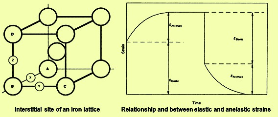
Fig 1 Iron lattice and time dependence of elastic and anelastic strains
The combination of the elastic strain and anelastic strain cause Young’s modulus, as determined during tensile testing, is loading-rate (or strain-rate) dependent and can produce damping or internal friction in the material subjected to cyclic or vibratory loads. Anelastic strain is one cause of stress relaxation during tensile testing when the test sample is loaded and held at a fixed displacement. This stress relaxation is often called an ‘elastic aftereffect’ and results due to a time dependent load drop since the load necessary to maintain the fixed displacement decreases as atoms move to favoured sites and anelastic deformation takes place. This elastic aftereffect demonstrates the importance of time or loading rate on test results.
The total reversible strain which accompanies the application of a tensile load to a test sample is the sum of the elastic and anelastic strains. Rapid application of the load causes the anelastic strain to approach zero (the testing time is not sufficient for anelastic strain), thus the total strain during loading is equal the true elastic strain. Very slow application of the same load allows the anelastic strain to accompany the loading process, thus the total reversible strain in this testing exceeds the reversible strain during rapid loading. The measured value of Young’s modulus in the low strain rate testing is lower than that measured in the high strain rate testing, and hence the measured modulus of elasticity is strain rate dependent. The low value of Young’s modulus is termed as the ‘relaxed modulus’ and the modulus measured at high strain rates is termed the ‘unrelaxed modulus’.
Damping capacity
Tensile testings and cyclic loadings are often made at strain or loading rates which are in-between those needed for fully relaxed behaviour and those required for fully unrelaxed behaviour. Hence, on either loading or unloading, the initial or short time portion of the stress-strain curve produces unrelaxed behaviour whereas the later, longer time portions of the curve produces more relaxed behaviour. The transition from unrelaxed to relaxed behaviour produces a loading-unloading hysteresis in the stress-strain curve. This hysteresis represents an energy loss during the loading-unloading cycle. The amount of energy loss is proportional to the magnitude of the hysteresis. Such energy loss which can be attributed to anelastic effect within the material lattice is termed ‘internal friction’. Internal friction plays a key role in the ability of the iron and steel materials to absorb vibrational energy. Such absorption can cause the temperature of the material to rise during the loading-unloading cycle. One measurement of the susceptibility of the material to internal friction is the damping capacity.
Since anelasticity and internal friction are dependent on time and temperature, the damping capacity of the material is both temperature and strain-rate dependent. Internal friction and damping play key roles in the response of the material to vibrations. Iron and steel materials tested under condition which causes significant internal friction during loading-unloading cycle undergo large energy losses and are said to have high damping capacities. These materials are useful for the absorption of vibrations. Example is gray cast iron which has a very high damping capacity and is regularly being used for the bases of instruments and equipment which are to be isolated from area vibrations. Mill stand, lathes, and presses etc. normally use cast iron bases to reduce transmission of machine vibrations to the floor and surrounding area. However, a high damping capacity is not always a useful material quality.
Anelasticity, damping, stress relaxation, and the elastic moduli of the iron and steel materials are also dependent on the microstructure of the material as well as on test conditions. These properties are not usually determined by tensile testing techniques. However, these properties, as well as the machine parameters, influence the shape of the stress-strain curve.
The proportional limit
The apparent stress necessary to produce the onset of curvature in the tensile stress-strain relationship is the proportional limit (PL). The PL is defined as the maximum stress at which strain remains directionally proportional to stress. Departure from proportionality can be attributed to anelasticity and/or the initiation of plastic deformation. The ability to detect the occurrence of these phenomena during tensile testing is dependent on the accuracy with which stress and strain are measured. The measured value of the PL decreases as the accuracy of the measurement increases. Since the measured value of PL is dependent on testing accuracy, the PL is not generally reported as a tensile property of the material. Also, the value of PL has little or no utility in the selection, qualification, and use of the materials for engineering applications. A far more reproducible and practical stress is the YS of the material.
Yielding of materials and the onset of plasticity
The YS of the iron and steel materials can be defined as the stress at which the material shows a specified deviation from the proportionality between stress and strain. Very small deviation from proportionality can be caused by anelastic effect, but this departure from linear behaviour is fully reversible and does not represent the onset of significant plastic (nonreversible) deformation or yielding. Theoretical value of YS is calculated from equation YS = E/2p where E is modulus of elasticity and p is the value of Pi (3.14159). Theoretically, yielding does not take place unless the applied stress is a significant fraction of the modulus of elasticity. This estimate for yielding generally over predicts the measured YS by a factor of at least 150 in case of iron and steel materials. The discrepancy between the theoretical and actual YS is due to the motion of dislocations. Dislocations are defects in the crystal lattice, and the motion of these defects is a primary mechanism of plastic deformation. The technique which alters the YS of the material is dependent on defect interactions to alter the ease of dislocation motion.
Dislocation mobility is dependent on the alloy content, the extent of cold work, the size, shape, and distribution of inclusions and second phase particles, and the grain size of the material. The strength increases as alloy content increases, since the alloy (or impurity) atoms interact with dislocations and prevent subsequent motion. Thus, this type of strengthening results from the interaction of point defect with line defect.
Cold working is an effective technique for increasing the strength of iron and steel materials. This strengthening mechanism is effective since the number of dislocations in the material increases as the percentage of cold work increases. These additional dislocations constrain the continued motion of other dislocations. Cold working is an example of strengthening due to the line defects interacting with other line defects in a crystal lattice. Rolling, stamping, forging, drawing, swaging, and even extrusion can be used to provide the necessary cold work.
Grain and phase boundaries also block dislocation motion. Thus, the YS increases as the number of grain boundaries increases and/or as the percentage of second phase in the structure increases. A decrease in the grain size increases the number of grain boundaries per unit volume, thus increasing the density of area defects in the material lattice. Since interactions between area defects and line defects restrict dislocation mobility, the YS increases as the grain size decreases and as the number of second-phase particles increases.
Iron and steel materials show a wide range of YS due to the different strengthening mechanisms. The range of YS is dependent on the grain size, percentage of cold working, distribution of second-phase particles, and other relatively easily quantified micro-structural parameters. The value of the micro-structural parameter depends on the thermo-mechanical history of the material. Hence knowledge of the important metallurgical variables is almost a necessity for intelligent interpretation of the YS data and for the design and utilization of structures and components made from these materials.
The most common definition of YS is the stress necessary to cause a plastic strain of 0.002 mm/mm. This strain represents a readily measurable deviation from proportionality, and the stress necessary to produce this deviation is the 0.2 % offset YS. A significant amount of dislocation motion is needed before a 0.2 % deviation from linear behaviour is reached. Hence, during standard tensile testing, the 0.2 % offset yield strength is almost independent of testing machine variables, gripping effects and reversible nonlinear strains such as anelasticity. Due to this independence, the 0.2 % offset yield strength is a reproducible property which is used in the description of the mechanical properties of iron and steel materials. Still, it is important to know that the magnitude of the YS, or any other tensile property, is dependent on the defect structure of the material tested. Hence, the thermo mechanical history of the material is to be known if YS is to be used a meaningful design parameter.
Yield point
The onset of dislocation motion in some iron and steel materials, mainly low C steels tested at room temperature, is sudden, rather than a relatively gradual process. This sudden occurrence of yielding makes the representation of yielding by a 0.2 % offset method impractical. Due to the sudden yielding, the stress-strain curve in mild steel has a yield point (YP), and the YS of mild steel is described by lower yield stress. The YP develops due to the interactions of the solute (dissolved) atoms and dislocations in the solvent (host) lattice. The solute-dislocation interaction in mild steels involves C migration to and interaction with dislocations. Since the interaction causes the concentration of solute to be high in the vicinity of the dislocations, the YP point is said to develop due to the segregation of C to the dislocations.
Many of the interstitial sites around dislocations are enlarged and hence are the low energy or favoured sites for occupancy by the solute atoms. When these enlarged sites are occupied, a high concentration or atmosphere of solute is associated with the dislocation. In mild steel, the solute segregation produces C rich atmosphere at the dislocation. Motion of the dislocation is restricted since such motion needs the separation of the dislocation from the C atmosphere. As soon as the separation takes place, the stress required for continued dislocation motion decreases and, in tensile testing, the lower YS are reached. This yielding process involves dislocation motion in localized regions of the testing sample. Since dislocation motion is plastic deformation, the regions in which dislocations moved represent deformed regions or bands in the material. These localized, deformed bands are called Lu¨ders bands. Once initiated, additional strain causes the Lu¨ders bands to propagate throughout the gauge length of the testing sample.
This propagation takes place at a constant stress which is the lower YS of the steel. When the whole gauge section has yielded, the stress-strain curve begins to rise because of the interaction of dislocations with other dislocations, and strain-hardening initiates. The existence of YP and Lu¨ders band is important because of the impact of the sudden softening and localized straining on processing techniques. As an example, sudden localized yielding causes jerky flow of material. Jerky material flow is undesirable in a drawing operation since the load on the drawing equipment changes rapidly, causing large release of energy which is to be absorbed by the processing equipment. Also, localized Lu¨ders strains produce stretch marks in materials during stamping process. These stretch marks are termed ‘stretcher strains’ and are readily apparent on stamped surfaces. This deteriorates the appearance of the surface and reduces the utility of the component. If material which does not have YP is stamped, smooth surface is developed since the strain-hardening process spreads the deformation uniformly throughout the material.
Effects of grain size on yielding
The iron and steel materials used in the structural applications are polycrystalline. These materials typically contain a large number of microscopic crystals or grains. The size of the grains is difficult to define precisely because the three dimension shape of the grain is quite complex. If the grain is assumed to be spherical then the grain diameter (d) can be used to specify the size. For specifying of the grain size more precisely, it normally includes the mean grain intercept (I), and the ratio (Sv) of grain boundary surface to grain volume. These two parameters can be established through quantitative metallographic techniques.
However, for historical reasons, the parameter d is the most common measure used to describe the influence of grain size on the YS of iron and steel materials. This influence is often quantified through the Hall-Petch relationship whereby YS is related to grain size through an empirical equation.
Grain boundaries act as barriers to dislocation motion, causing dislocations to pile up behind the boundaries. This pileup of dislocations concentrates stresses at the tip of the pileup, and when the stress is sufficient, additional dislocations can be nucleated in the adjacent grain. The magnitude of the stress at the tip of a dislocation pileup is dependent on the number of dislocations in the pileup. The number of dislocations which are contained in a pileup increases with increasing grain size due to the larger grain volume. This difference in the number of dislocations in a pileup makes it easier for new dislocations to be nucleated in a large grain material than in a fine grain material of comparable purity, and this difference in the ease of dislocation nucleation extrapolates directly to the difference in YS.
Effect of cold working and the strain hardening
Plastic deformation of iron and steel materials at temperature higher than the recrystallization temperature is hot working while the plastic deformation of these materials at temperature lower than the recrystallization temperature is cold working. These materials during tensile testing above the recrystallization temperature do not show significant strain hardening, and the tensile YS become the maximum stress which the material can effectively support. A stress-strain curve for these materials shows that the stress necessary to cause continued plastic deformation increases as the tensile strain increases.
The stress necessary for continued deformation is frequently designated as the flow stress at the specific tensile strain. The increasing flow stress with increasing strain is the basis for increasing the strength of the materials by cold working. The effect of grain size on the strength of the material is retained throughout the cold working process. The fact that the grain size dependence of strength is retained throughout the strain hardening process establishes the possibility for interaction among the various strengthening mechanisms in these materials. As an example, cold working causes strength increase through the interaction between point defect and dislocation, and these effects are additive to the effects of alloying.
Also, strength is not the only tensile property affected by the cold working process. Ductility decreases with increase in the cold working, and, if cold working is too extensive, steel bar can crack and fracture during the cold working. The overall effect of cold working on strength and ductility is that the increase in strength and decrease in ductility causes the area under the stress-strain curve to decrease. This is important since this area represents the work or energy needed to fracture the steel bar, and the result of the tensile testing show that this energy decreases as the percentage of cold working increases.
Cold working, whether by rolling, drawing, stamping, or forging, changes the microstructure. The resulting grain shape is determined by the direction of metal flow during processing. The grains in the cold rolled sample are elongated and flattened, thus changing from the semispherical grains to the pancake-shape grains. A rod drawing process produces needle shaped grains. In addition to the changes in grain shape, the grain interior is distorted by cold working operations. Bands of high dislocation density (deformation bands) develop, twin boundaries are bent, and grain boundaries become rough and distorted. Since the deformation induced changes in microstructure are anisotropic, the tensile properties of wrought steel material is often anisotropic. The strain hardened microstructures and the accompanying mechanical properties which result from cold working can be significantly altered by annealing. The microstructural changes which are introduced by heating to the higher temperatures are dependent on both the time and temperature of the annealing. This temperature dependence results since atom motion is needed for the annealing to be effective.
Tensile strength
The ability to strain harden is one of the normal characteristics in mechanical behaviour which separate iron and steel materials from other engineering materials. Not all metallic materials show this characteristic. As an example, chromium (Cr) is very brittle and fractures in a tensile test without evidence of strain hardening. The stress-strain curves for the brittle materials are similar to those of the ceramic materials. Fracture occurs before significant plastic deformation takes place. Such brittle materials have no real YS, and the fracture stress is the maximum stress that the material can support. However, iron and steel materials undergo plastic deformation prior to fracture, and the maximum stress which the material can support is appreciably higher than the YS. This maximum stress (based on the original dimensions) is the ultimate or tensile strength (TS) of the material.
The margin between the YS and the TS provides an operational safety factor for the iron and steel materials in structures. Other than this safety margin, the actual value of TS has very little practical use. The ability of a structure to withstand complex service loads bears little relationship to TS, and structural design is to be based on yielding. The TS is easy to measure and is often reported since it is the maximum stress on a stress-strain curve. Engineering codes sometimes specify that the material is to meet certain TS requirement.
Historically, TS, with experience based reductions to avoid yielding, was used in design calculations. As the accuracy of measurement of stress-strain curves improved, utilization of TS reduced, and by the 1940s several of the design codes were based on yielding. There is a large empirical database which correlates TS with hardness, fatigue strength (FS), stress rupture, and mechanical properties. These correlations, historical code requirements, and the fact that structural designs incorporating brittle materials are to be based on TS provide the technical basis for the continued utilization of TS as design criteria.
Cold working and other strengthening mechanisms of iron and steel materials do not increase TS as rapidly as they increase the YS. Hence, strengthening processes often are accompanied by a reduction in the ability to undergo plastic strain. This reduction decreases the ability of the material to absorb energy prior to fracture and, in many cases, is important for the successful utilization of these materials. Analysis of the tensile behaviour of these materials can provide insight into the energy absorbing abilities of the material.
Toughness
The ability to absorb energy without fracturing is due to the toughness of the material. In most of the cases, fractures of iron and steel materials are initiated at pre-existing defects. These defects can be small enough to be elements of the microstructure or, when slightly larger, can be macroscopic cracks in the material or, in the extreme case, visually observable discontinuities in the structure. A tough steel material resists the propagation of defects through processes such as yielding and plastic deformation. Maximum of this deformation takes place near the tip of the defect. Since fracture involves both tensile stress and plastic deformation, or strain, the stress-strain curve can be used to estimate material toughness. However there are specific tests designed to measure material toughness. Majority of these tests are conducted with pre-cracked samples and include both impact and fracture mechanics. Toughness calculations based on tensile behaviour are estimates and are not to be used for design.
The area under a stress-strain curve is a measure of the energy absorbed by the material during tensile testing. This area is a rough estimate of the toughness of the material. Since the plastic strain associated with tensile deformation of iron and steel materials is typically several orders of magnitude greater than the accompanying elastic strain, plasticity or dislocation motion is very important to the development of toughness. This is demonstrated by the stress-strain curves for a brittle, a semi-brittle, and a ductile material. Brittle fracture takes place with little or no plastic strain, and thus the area (A) under the stress-strain curve is given by the equation A = 0.5 Se. Estimation of the fracture energy from the typical tensile properties of mild steel test sample with a YS of 205 MPa, TS of 415 MPa, and strain to fracture value of 0.3, gives 1.12 J/ cu mm of gauge section of the test sample.
The ratio of the energy for ductile fracture to the energy for brittle fracture is 900. This ratio increases with increasing strain to fracture and with increasing strain hardening. The area and energy relationship is only approximate. The utility of such toughness estimates is the ease with which testing can be done and the insight that the estimates provide into the importance of plasticity to the prevention of fracture. Further, a plastic strain of only 0.01 % can have a remarkable effect on the ability of the material to absorb energy without fracturing.
Toughness is a very important property for many structural applications. Crane arms, ship hulls, axles, gears, and couplings are all required to absorb energy during service. The ability to withstand earthquake loadings, system overpressures, and even minor accidents also need material toughness. Increasing the strength of iron and steel materials usually reduces ductility and, in many cases, reduces toughness. Thus, increasing the strength of the material can increase the likelihood of service-induced failure when material toughness is important for satisfactory service.
This is seen by comparing the areas under the two stress-strain curves in Fig 2. The cross-hatched areas in Fig 2 show another tensile property which is the modulus of resilience. Modulus of resilience can be measured from tensile stress-strain curves. The ability of iron and steel materials to absorb energy through elastic process is the resilience of the material. The modulus of resilience is defined as the area under the elastic portion of the stress-strain curve. Increasing the YS and/or decreasing Young’s modulus increase the modulus of resilience and improve the ability of these materials to absorb energy without undergoing permanent deformation.
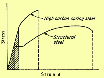
Fig 2 Comparison of the stress-strain curves for high and low toughness steels
Material ductility
Material ductility during tensile testing is generally established by measuring either the elongation to fracture or the reduction in area (RA) at fracture. In general, measurement of ductility is of interest in three ways namely (i) to indicate the extent to which a steel can be deformed without fracture in metalworking operations such as rolling, forming, or extrusion, (ii) to indicate to the designer, in a general way, the ability of the steel to flow plastically before fracture, and (iii) to serve as an indicator of changes in impurity level or processing conditions. Ductility measurement is to be specified to assess material quality even though no direct relationship exists between the ductility measurement and the performance.
Tensile ductility is a very useful measure during the assessment of material quality. Many codes and standards specify minimum values for tensile ductility. One reason for these specifications is the assurance of adequate toughness without the necessity of requiring a more costly toughness specification. Most changes in material composition and/or processing conditions produce changes in tensile ductility. Further, the metal-working features of iron and steel materials are better correlated with the ability to strain harden than with the ductility of the material. The strain-hardening abilities of many iron and steel materials used for engineering service have been quantified through the analysis of true stress-strain behaviour.
True stress-strain relationship
Conversion of engineering stress-strain behaviour to true stress-strain relationship shows that the maximum in the engineering stress-strain curve results from tensile instability, not from a decrease in the strength of the material. The drop in the engineering stress-strain curve is artificial and occurs only because stress calculation is based on the original cross-sectional area. Both testing and analysis show that, for most iron and steel materials, the tensile instability corresponds to the onset of necking in the test specimen. Necking results from strain localization. Hence, once necking is initiated, true strain cannot be calculated from sample elongation. Due to these and other analytical limitations of engineering stress-strain data, if tensile data is used to understand and predict metallurgical response during the deformation associated with fabrication processes, then true stress-true strain relationship is favoured.
The deformation which can be accommodated without fracture in a deep drawing operation varies with the material. As an example, austenitic stainless steel can be successfully drawn to 50 % RA whereas ferritic steel may fail after around 20 % to 30 % RA in similar drawing operations. Both types of steels undergo in excess of 50 % RA during tensile testing. This difference in drawability correlates with the strain-hardening exponent (n) and therefore is apparent from the slope of the true stress-strain curves for the two steels.
The n values for ferritic and austenitic steels are typically 0.25 and 0.5 respectively. A perfectly plastic material has a n value of zero and a completely elastic solid has a n value of one. Most iron and steel materials have n values between 0.1 and 0.5. Strain-hardening exponents correlate with the ability of dislocations to move around or over dislocations and other obstacles in their path. Such movement is termed ‘cross slip’. When cross slip is easy, dislocations do not pile up behind each other and n value is low. Mild steel is the example which undergoes cross slip easily. The n value increases as cross slip becomes more difficult. Cross slip is very difficult in austenitic stainless steel and the n value for this steel is around 0.5.
Tensile samples, sheets, plates, wires, rods, and other metallic sections have spot-to-spot variations in section size, YS, and other microstructural and structural in-homogeneities. Plastic deformation of these materials initiates at the locally weak regions. In the absence of strain hardening, this initial plastic strain reduces the net section size and focuses continued deformation in the weak areas. However, strain hardening causes the flow stress in the deformed region to increase. This increase in flow stress increases the load necessary for continued plastic deformation in the area and causes the deformation to spread throughout the section. The higher the n value, the greater is the increase in low stress and the greater is the tendency for plastic deformation to become uniform. This tendency has a major impact on the fabricability of the iron and steel materials.
As an example, the maximum RA which can be accommodated in a drawing operation is equal to the n value as determined from the true stress-strain behaviour of the material. Because of such correlation, the effect of process variables such as strain rate and temperature can be evaluated through tensile testing. This provides a basis to estimate the effect of process variables without direct, in-process assessment of the variables.
Temperature and strain rate effects
The YS of most iron and steel materials increases as the strain rate increases and decreases as the temperature increases. This dependence results from a combination of several metallurgical factors. As an example, dislocations are actually displacements and hence cannot move faster than the speed of sound. Also, as dislocation velocities approach the speed of sound, cross slip becomes increasingly difficult and the n value increases. This increase in the n value increases the flow stress at any given strain, thus increasing the YS of the material. A decrease in ductility and even a transition from ductile to brittle fracture can also be associated with strain rate induced increases in the YS.
In many respects, decreasing the temperature is similar to increasing the strain rate. The mobility of dislocations decreases as the temperature decreases, and hence for most of the iron and steel materials, the strength increases and the ductility decreases as the temperatures are lowered. If the reduction in dislocation mobility is adequate, the ductility can be reduced to the point of brittle fracture. Iron and steel materials which show a transition from ductile to brittle fracture when the temperature is lowered are not to be used for structural application at temperature which is below this transition temperature.
Dislocation motion is inhibited by interaction between dislocation and by the alloying or impurity (alien) atom. The effect of this interaction is both time and temperature dependent. The interaction acts to increase the YS and limit ductility. The process is most effective when there is enough time for alien atom to segregate to the dislocation and when dislocation velocity is almost equal to the diffusion velocity of the alien atom. Hence, at any given temperature, dislocation- alien atom interaction is at a maximum at some intermediate strain rate. At low strain rate, the alien atom can diffuse as rapidly as the dislocation moves and there is little or no tendency for the deformation process to force a separation of dislocation from its solute atmosphere. At high strain rates, once separation has been achieved, there is no adequate time available for the atmosphere to be re-established during the testing period. Atom movement increases with increasing temperature, thus the strain rate which allows dislocation-alien atom interaction to occur is temperature dependent. Since this interaction limits ductility, the elongation in tensile testing can show a minimum at intermediate test temperature where such interaction is very effective.
The effect of time dependent dislocation-alien atom interaction on the stress-strain curve of iron and steel materials is termed as ‘strain aging’ and ‘dynamic strain aging’. Strain aging is usually apparent when tensile testing of the material which shows a sharp YP, is interrupted. If the testing sample is unloaded after being strained past the YP, through the Lu¨ders strain region and into the strain-hardening portion of the stress-strain curve, either of two behaviours are observed when the tensile test is resumed.
If the sample is reloaded in a short period of time, the elastic portion of the reloading curve is parallel to the original elastic loading curve and plastic deformation resumes at the stress level which was reached just before the testing was interrupted. However, if the time between unloading and reloading is enough for segregation of alien atom to the dislocation, the YP reappears and plastic strain is not reinitiated when the unloading stress level is reached. This reappearance of the YP is strain aging, and the strength of the strain aging peak is dependent on both time and temperature since solute-atom diffusion and segregation to dislocation is needed for the peak to develop. If tensile strain rate is in a range where solute segregation can occur during the testing, dynamic strain aging is observed. Segregation pins the previously mobile dislocation and increases the flow stress, and when the new, higher flow stress is reached the dislocation is separated from the solute atmosphere and the flow stress decreases. This alternate increase and decrease in flow stress causes the stress-strain curve to be serrated.
Serrated flow is usual in mild steel since it contains mobile, alloy or impurity element. This effect has been initially studied in detail by Portevin and LeChatelier and is often called the Portevin-LeChatelier effect. Processing condition is to be selected to avoid strain aging effect. This selection essentially involves the control of processing strain rate and temperature.
Special testing methods
The tensile test provides basic information concerning the response of iron and steel materials to mechanical loading. Testing temperature and strain rate (or loading rate) normally is controlled due to the effects of these variables on the metallurgical response of the sample. The tensile testing usually measures strength and ductility. These parameters are frequently sensitive to the sample configuration, testing environment, and the manner in which the testing is conducted. Special tensile testing methods have been developed to measure the effect of testing/sample conditions on the strength and ductility of iron and steel materials. These testing methods include the notch tensile test and the slow-strain-rate tensile test.
Notch tensile testing
Iron and steel materials used in engineering applications is often required to withstand multi-axial loading and high stress concentration because of component configuration. Standard tensile testing measures material performance in a smooth bar sample exposed to uniaxial load. This difference between application and testing sample can reduce the ability of the standard tensile testing to predict material response under anticipated condition of application. Also, the reduction in ductility usually induced by multi-axial loading and stress concentration may not be visible in the testing result. The notched tensile testing therefore has been developed to minimize this weakness in the standard tensile testing and to examine the behaviour of material in the presence of flaws, notches, and stress concentrations.
The notched tensile sample usually contains a 60 deg notch which has a root radius of less than 0.025 mm. The stress state just below the notch tip approaches tri-axial tension, and for ductile steels this stress state normally increases the YS and decreases the ductility. This increase in YS results from the effect of stress state on dislocation dynamics. Shear stress is needed for the dislocation motion. Pure tri-axial loading does not produce any shear stress. Hence, dislocation motion at the notch tip is limited and the YS value is increased. This constraint in dislocation motion also reduces the ductility of the notched sample. For low ductility steels, the notch-induced reduction in ductility can be so severe that failure takes place before the 0.2 % offset YS is reached.
The sensitivity of iron and steel materials to notch effect is termed as the ‘notch sensitivity’. This sensitivity is quantified through the ratio of notch strength to smooth bar TS. Material which is notch sensitive has ratio less than one. Smooth bar tensile data for these materials does not satisfactory predicts the material behaviour under service conditions. Tough ductile material often is notch-strengthened and has notch sensitivity ratio greater than one, thus the standard tensile testing is a conservative predictor of performance for this material.
Slow strain rate testing
Testing environments can also have adverse effects on the tensile behaviour of iron and steel materials. The characterization of environmental effect on material response can be accomplished by conducting the tensile testing in the environment of interest. Since the severity of environmental attack usually increases with increasing time, tensile testing designed to determine environmental effects often is conducted at very low strain rate. The low strain rate increases the testing time and maximizes exposure to the testing environment. This type of testing is termed either ‘slow strain rate testing’ (SSRT) or ‘constant extension rate testing’ (CERT). Exposure to the aggressive environment can reduce the strength and/or ductility of the testing sample. This reduction can be accompanied by the onset of surface cracking and/or a change in the fracture mode. SSRT or CERT study which displays harmful effects on the tensile behaviour, establishes that the test material is susceptible to environmental degradation.
This susceptibility can cause concern over the utilization of the material in that environment. Conversely, the test can show that the tensile behaviour of the material is not influenced by the environment and is therefore suitable for application in that environment. SSRT or CERT can be used to screen materials for potential service exposures and/or examine the effects of anticipated operational changes on the materials used in process systems. In either case, the intent is to avoid materials utilization under conditions which may degrade the strength and ductility and cause premature failure. In addition to the tensile data, evidence of adverse environmental effect can also be found through examination of the fracture morphology of the testing samples of CERT and SSRT.
Fracture characteristics
Tensile fracture of ductile iron and steel materials generally initiates internally in the necked portion of the tensile bar. Particles such as inclusion, dispersed second phase, and/or precipitate can serve as the nucleation sites. The fracture process begins by the development of small hole, or micro-void, at the particle-matrix interface. Continued deformation enlarges the micro-void until, at some point in the testing process, the micro-void contacts other micro-void and coalesces. This process is termed ‘micro-void coalescence’ and gives rise to the dimpled fracture surface topography characteristic of the ductile failure processes.
The surface topography of a brittle fracture differs significantly from that of micro-void coalescence. Brittle fracture generally initiates at imperfections on the external surface of the material and propagates either by trans-granular cleavage like process or by separation along grain boundary. The resultant surface topography is either faceted, perhaps with the river like pattern typical of cleavage, or inter- granular, producing a ‘rock candy’ like appearance. The testing material can be inherently brittle or brittleness can be introduced by heat treatment, lowering of the testing temperature, the presence of an aggressive environment, and/or the presence of a sharp notch on the testing sample.
The temperature, strain rate, test environment, and other conditions, including sample surface finish for tensile testing, are generally well established. An understanding of the effects of such testing parameters on the fracture characteristics of the test sample can be very useful in the determination of the susceptibility of iron and steel materials for degradation during the fabrication or during the application. Typically, any heat treatment or testing condition which causes the fracture process to change from micro-void coalescence to a more brittle fracture mode reduces the ductility and toughness of the material and can promote early fracture under selected service conditions. Since the fracture process is very sensitive to both the metallurgical condition of the sample and the conditions of the tensile testing, characterization of the fracture surface is an important component of many tensile-testing programs.

Leave a Comment