Salamander Tapping for Capital Repairs of Blast Furnace
Salamander Tapping for Capital Repairs of Blast Furnace
A salamander means all liquid and solidified materials in the hearth of a blast furnace below the tap hole. The salamander includes liquid iron and slag and mixtures of solid iron, slag and coke/carbon. During the normal operation of the blast furnace, the furnace bottom and hearth contains the ‘dead-man’ and the salamander.
When the blast furnace is to be relined, it is necessary that the furnace is emptied completely by removing all the constituents of the bottom and the hearth. It is also desirable to remove these constituents during partial relining of the furnace or during the repairs of the tap-hole. This provides safer working conditions during these partial repairs and prevents damage to the hearth refractories as a result of cyclic cooling and heating movements. The removal of all the constituents of the bottom and the hearth of the furnace is carried out usually by salamander tapping. The salamander tapping is usually done at preferably the lowest level where liquid iron can be expected in the blast furnace hearth.
Salamander tapping of a blast furnace is the final tapping after the furnace is blown down in order to drain the last liquid iron from the furnace hearth. Because of its rare occurrence a salamander tapping represents in most of the steel plants a specialized job which requires a lot of preparation.
A solidified salamander is normally difficult to remove especially if there is titanium in it. A large quantity of solid salamander can delay the critical path of the capital repairs of the blast furnace by a number of days or even by weeks. For the removal of the solidified salamander often requires oxygen lancing and even explosives. These types of removal also cause health and safety hazards.
The tapping of the liquid salamander is generally carried out immediately after the blow-down of the furnace. It is important to maximize the yield during the salamander tapping of the blast furnace in order to minimize the amount of the residual solids remaining in the furnace. A successful salamander tapping normally provides clean hearth to the capital repairs team. This not only minimizes delays but also contributes to safer working conditions during the refractory demolition. Clean hearth also inspires the capital repairs team’s spirit.
Total removal of the hearth contents of the blast furnace for the successful tapping of the salamander requires pre-preparation and monitoring activities in the blast furnace to increase temperature and fluidity. These activities are to be coupled with the use of well-tried drilling and lancing techniques.
Generally due to the normal construction of a blast furnace and its cast house, the salamander tap hole is to be positioned somewhere close under the cast house floor in a difficult to reach area, full with piping, cables, etc. These difficult to access area may also be dangerous area for the people who are drilling or lancing the salamander, because of insufficient or poorly accessible escapes routes.
The emphasis on safety and environment is the driving force to improve the process of salamander tapping. While draining as much liquid iron from the hearth as possible is the major goal, other issues which are important are (i) location of the salamander tap hole, (ii) environmental aspects of salamander tapping, and (iii) tapping of the maximum of liquid salamander iron.
It is necessary to locate the best position of the salamander tap hole. In the olden days the exact position of the salamander was usually unknown, due to a lack of information on the blast furnace hearth interior and thus on the position of the wear line. Without any or insufficient data from thermocouples, it was difficult to determine the optimal position to drill or lance the salamander tap hole. Professional experience was leading in order to determine the drill location and angle to hit the salamander. More than once a number of holes had to be drilled and lanced before the salamander was hit and started to tap.
These days with modern blast furnace hearths being more and more equipped with dense thermocouple grids, thermal calculation of the position of the wear line, and hence of the salamander position has now become possible. Densifying of the thermocouple grid has improved the calculation accuracy. Now instead of guessing of the location where the salamander may be hit, it is now replaced by knowing where the drill hits the wear line and, hence, from where the salamander is expected. An additional advantage of a more precise location is the possibility to improve the engineering of the setting round the salamander tapping.
The improvised salamander tapping in the past not only resulted in a lot of sparkling iron, but also in large clouds of smoke. With growing attention for the environmental aspects, these dark clouds have become more and more unwanted. The improved estimation of the wear line position allowed for more detailed engineering of the salamander tapping and possibility of introducing the dedusting facilities at the salamander tap hole. Temporary exhaust hoods and duct work are now engineered, constructed, and connected to the existing dedusting system, in order to make a salamander tapping not more polluting then a regular tap. This eliminates the enormous clouds of red smoke, which hampers also the view on the tapping.
In the past, salamanders were tapped after the blow down and after the blast furnace were completely taken off blast. As a result, the salamander had only its own ferrostatic pressure as the driving force to come out of the furnace. Not drilling the salamander tap hole completely through into the liquid and lancing the last part, results in an undefined tap hole diameter and sometimes in slowly running casts. These slowly running casts may also be retarded by a decreased hot metal temperature of the salamander, caused by the effect of the hearth cooling system during the waiting time between the end of the blow-down and of the start salamander tap. Now it is a usual practice to keep some blast pressure on the furnace as an additional driving force to drain out more liquid.
There are several prerequisites for the salamander tapping to be successful. These include (i) a maximum ratio between liquid and solid salamander, (ii) low viscosity/high temperature of the liquids, (iii) correct setting of the salamander tapping angle(s) and elevation(s), (iv) good blow-down results, and (v) efficient execution of the actual salamander tapping activities.
The preparations for the salamander tapping start 3 months to 6 months prior to the putting down the blast furnace for the capital repairs and include actual salamander tapping activities and process modifications. The process modifications must result in favourable conditions for optimum salamander tapping. One of the main targets relates to melting/liquefaction of the existing solid salamander and increasing its fluidity to obtain smooth flow. The fluidity of the liquids increases with temperature and can be checked during tapping. Also the silicon content of the hot metal can be monitored since it gives a fairly good indication of the thermal state of the hearth. The bottom and hearth refractories are to be directly exposed to liquids for the effective salamander tapping.
The thermal state of the hearth can also be monitored by analyzing key readings of the thermocouple. Salamander liquefaction basically relates to increasing the thermal state of the hearth. It encompasses all activities contributing to this target, and higher readings of the thermocouple reflect an increase in the thermal state of the hearth. The process of liquefaction is determined both by local hot metal flow and temperature, but flow is the more important of the two. Therefore, the focus is to be directed towards influencing hot metal flow in the hearth. This is usually not a standard practice in blast furnace operation.
Salamander liquefaction is thus basically the opposite of hearth protection for campaign extension. Typically the liquefaction methodologies for the salamander include (i) reduction of the bottom and sidewall cooling, (ii) targeting of higher productivity in the blast furnace, (iii) strict implementation of tapping between alternating tap holes, (iv) increasing of the silicon level in the hot metal, (v) charging of higher sized coke, (vi) removal of TiO2 from the burden.
The number of tap holes needed for a successful salamander tapping is an important decision which is required to be taken. Usually this number depends on the diameter of the hearth. As per thumb rule, usually one tap hole is considered when hearth diameter is less than 9 meters, two numbers of tap holes are considered when the hearth diameter is in the range of 9 m to 12 m and three numbers of tap holes are considered if the hearth diameter is more than 12 metres.
Multiple angles and elevations are defined at each salamander tapping position. In general, multiple positions increase the salamander tapping yield as the chance of success is increased and drainage is improved. The determination of the right number of salamander tapping positions is a balance between costs and risks so prior assessment of conditions may also prevent multiple salamander tapping positions. The position of the tapping point(s) around the circumference is normally determined by access conditions, runner lay-out(s) and ladle/sand bed positions.
Normally multiple positions are preferred as drilling can commence simultaneously at two positions using two teams to save time. It is often seen that the yield at one position is zero, while the yield at the other position is large. This may be caused by local internal obstacles/barriers preventing smooth effusion of liquids. Multiple positions, therefore, reduce the risk of low/zero yields.
The correct setting of the salamander tapping angles and elevations is normally a compromise between theoretical calculations and considerations, and practical limits. Structural elements on site such as piping and cabling may limit access conditions and the elevation(s) of the ladle track(s) may inhibit selection of the most optimum theoretical salamander tapping elevation.
Usually it is common practice to determine at least three sets of increasing angles and elevations at each circumferential salamander tapping position. The vertical distance between the starting points is normally around 300 mm.
The entire salamander tapping process is normally executed within 24 hours. Generally a ‘go-stop’ criterion is followed to ensure that delays are prevented. As an example, a maximum of 4 hours is allotted drilling and lancing of one hole, irrespective of success. This requires specialized and experienced teams. The vertical distance between holes is to be around 300 mm to ascertain that the holes do not merge as effusion of liquids will increase the diameter of the ‘successful’ hole. A typical drilling diameter of the hole is around 80 mm which can increase to more than 200 mm during tapping. The minimum distance between two holes thus ensures that the holes stay intact. The length of the salamander tapping is normally limited to three metres so as to avoid clogging during tapping. There are chances of clogging if the length is higher than three metres.
Drilling methodologies
There is a wide variety of drilling equipment. Basically two types are well-known. They are (i) monorail mounted type, and (ii) runner manual type. Usually the manual type drilling equipment is preferable to maximize flexibility in setting angle(s) and elevation(s) while minimizing costs. There are several types of manual drilling equipment such as rock-drill and core-drill. A core-drill type, which can be better aligned and has an increased accuracy, is usually preferred. The power and control unit of the drilling unit is normally located outside the runner to maximize safety. The drill unit is mounted on a small rail, which is ‘hooked’ or welded to the shell and supported by the runner.
The salamander tapping activities include (i) removal of plate, (ii) installation of ramming, (iii) drying out of the ramming, (v) setting up of drilling equipment, (vi) salamander drilling, (vii) oxygen lancing, (viii) salamander tapping.
The salamander tapping activities are normally on the critical path of the capital repairs and are to be normally executed within 24 hours. The duration is mainly determined by the number of circumferential positions and associated crews of the workers. Repetitive drilling and oxygen lancing may be needed.
The typical duration for the above-mentioned activities is limited to 12 hours. Sometimes, pre-drilling is practiced during the pre-outage, but normally it does not contribute to accelerating the salamander tapping activities during the capital repairs. Installation of ramming at the runner/shell interface and subsequent drying out can be eliminated if a correct design is applied and associated works are executed during the pre-outage.
Salamander tapping is a critical activity during a capital repair of a blast furnace. A successful salamander tapping which results into a high yield of liquids removed before quenching and a low weight of solid residuals prevents long delays and improves health and safety conditions during the demolition of the refractories. Therefore, it is important to ensure that all available techniques and experiences are investigated and utilized. Fig 1 shows the lower salamander tapping at Blast furnace 2 of Visakhapatnam Steel Plant.
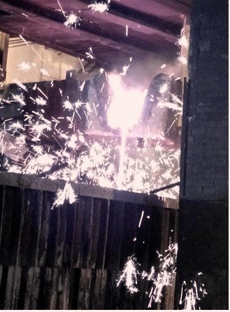
Fig 2 Lower salamander tapping at BF2 of Visakhapatnam Steel Plant

Leave a Comment