Non Destructive Testing of Steels
Non Destructive Testing of Steels
Non destructive testing (NDT) of steels is a group of analysis techniques used for evaluating the properties of steel materials, components, or welds without causing any damage to them. NDT techniques are used to detect and evaluate internal and surface defects (such as imperfections, discontinuities, and flaws etc.) that may cause failure under the designed operating conditions. These internal and surface defects may be the areas of lower integrity in comparison to other portion of the steel material or may consists of the presence of cracks, voids and other imperfections. NDT gives indirect yet valid results and, by definition, leave the test object fit for its intended use.
The terms non destructive examination (NDE), non destructive inspection (NDI), and non destructive evaluation (NDE) are also used for these testing techniques. Since there is no permanent alteration in the steel material being tested by NDT techniques, the NDT techniques are considered very important for material inspection. NDT saves both money and time in product evaluation, troubleshooting, and research.
NDT techniques constitute very specialized type of work that plays a critical function. These techniques need the service of highly specialized and qualified technicians who use sophisticated equipment and methods to evaluate areas of the steel component that are difficult or impossible to examine using the naked eye.
The NDT techniques are used for detecting defects during manufacture and fabrication as well as the defects developed during service of the steel components. However, it is not possible to detect all the possible defects by examining a component by NDT. Further in NDT, it is not the defect that is detected but the resulting effect on the material such as the modification of physical properties (attenuation to ultra sound or the electrical conductivity etc.). NDT techniques do not provide direct information but indirect information which need to be interpreted. Some NDT techniques are more direct and accurate than others.
There are a variety of NDT techniques which can be used to evaluate the steel materials, components, or welds. All NDT techniques share several common elements which include the following.
- There is some source of probing energy or some type of probing medium.
- There is a discontinuity that must cause a change or alteration of the probing medium.
- There is some means of detecting the change.
- There is some means of indicating the change.
- There is some means of observing and/or recording this indication so that an interpretation can be made.
The suitability of a technique of NDT for a given application is determined by considering the above elements. The source of the probing energy or probing medium is to be suitable for the test object and for detecting the defect or discontinuity sought. If present, a defect or discontinuity is to be capable of somehow modifying or changing the probing medium. Once changed, there is to be some way of detecting these changes. These changes to the probing medium by the discontinuity are to form some indication or otherwise be recorded. Finally, this indication are needed to be reviewed in order for it to be interpreted and to classify the discontinuity.
A number of NDT techniques have been developed, each one having advantages and limitations making it more or less appropriate for a given application. With the variety of NDT techniques available, it is important to select the technique which provides the necessary results. A combination of different NDT techniques can also be applied to provide assurance that the material or component is fit for use.
There are many different methods of NDT of steel materials and components. The more common NDT methods used for the evaluation of steel materials, components, or welds are (i) visual inspection, (ii) dye penetrant inspection, (iii) magnetic particle testing, (iv) radiographic inspection, (v) ultrasonic testing, and (vi) eddy current testing.
Visual inspection
Visual inspection is the most common, primary, inexpensive, and the oldest form of NDT examination. It relies upon the detection of surface imperfections using the eye, does not require any special testing equipment (except simple aids like magnifying glass), and can be completed more quickly and economically. However, due to subjective nature of visual inspections, variability of inspection results is common. It is not also possible to detect those defects by visual inspection which are not visible to the eyes. The three basic requirements for visual inspection are (i) good vision so as to be able to see the discontinuity which is being looked for, (ii) good lighting, the correct type of light is important, and (iii) experience, to be able to recognize the discontinuity.
Dye penetrant inspection
In dye penetrant inspection method a dye penetrant is used to detect surface defects by the ‘bleed-out’ of a penetrating medium against a contrasting background. The penetrating dye is applied to the pre-cleaned surface of the steel material to be tested and left for a prescribed period (dwell time) as capillary action draws it to any surface defects. The excess penetrant is then removed and a developer is applied. The developer reverses the capillary action and draws penetrant from the flaw. The resultant indications reveal the presence of the flaw so that it can be seen visually and defects can be observed and evaluated by the technician. Dye penetrant inspection method is shown in Fig 1.
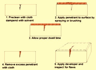
Fig 1 Dye penetrant inspection
There are two methods by which the dye penetrants are classified namely (i) by the type of indication produced, and (ii) the method of removal. dye penetrant testing results are also displayed in two ways, visible and fluorescent. The visible penetrant type produces a bold red line or strain indication against a white developer background when viewed under good white light conditions. The fluorescent penetrant produces a green, fluorescent indication when observed under an ultraviolet light. Since the human eye can more readily perceive a fluorescent indication than a visible indication, the use of fluorescent penetrant inspection is in a more sensitive test.
The second method of penetrant classification is based upon the way by which the excess penetrant is removed from the test surface. The penetrants are either water washable, solvent removable or post-emulsifiable. Water washable penetrants contain an emulsifier that allows the penetrant to be rinsed off using a low pressure water spray. Solvent removal penetrants require a solvent to remove the excess penetrant from the test surface. Post-emulsifiable penetrants are removed by adding an emulsifier after the penetrant dwell time.
This process is simple, versatile and cost efficient and can be further enhanced by using bright coloured or fluorescent dyes. The only drawback is that it can only detect surface defects.
Magnetic particle testing
Magnetic particle testing is used to locate surface and slight subsurface discontinuities or defects in ferromagnetic materials like steels. Such flaws present in a magnetized part causes a magnetic field (flux) to leave the part. If magnetic particles are applied to this surface, they will be held in place by the flux leakage to give a visual indication. While several different methods of magnetic particle tests can be used, they all rely on this same general principle. It is a very simple and cost-efficient process.
A magnetic particle test is conducted by creating a magnetic field in the part to be tested by applying the magnetic particles to the test surface. The process is done either in the field, using portable magnetic yokes, or in a shop using a magnetic bench. The bench is more efficient for large volumes of work.
Magnetic particle testing of steel is generally performed using a certain type of electromagnet. An electromagnet relies on the principle that there is a magnetic field associated with any electrical conductor. Either alternating current (AC) or direct current (DC) can be used to induce a magnetic field. The magnetic field created by AC due to the ‘skin effect’ is strongest at the surface of the test object. AC also provides greater particle mobility on the surface of the object allowing it to move about freely to locate areas of flux leakage, even though the surface of the object may be irregular. DC induces magnetic fields that have greater penetrating power and can be used to detect near surface discontinuities.
Radiographic inspection
Radiographic inspection is a technique based on using short wavelength electromagnetic radiation passing through the steel material. The traditional radiography method is the process of making a permanent record on radiographic film of test objects in order to detect defects. It is done by exposing the test object to either electrically generated x-rays or gamma-rays from a radiation source. Radiation from the source passes through the object and is recorded on radiographic film. The film is processed and the processed film (radiograph) is viewed by qualified technicians who are able to detect defects and anomalies in accordance with applicable codes and standards.
The principle used in this technique is that steel objects with areas of reduced thickness or lower material density allow more passage of the radiations, and therefore absorb less radiation. The radiation, which reaches the film after passing through the material, forms a shadow image on the radiograph. Areas of low absorption (slag, voids, and porosity) appear as dark areas on the radiograph while areas of high absorption (dense inclusions) appear as light areas on the radiograph.
Subsurface discontinuities that are readily detected by this method are voids, flaws, metallic and non-metallic inclusions, and cracks.
Recent advancements in radiographic inspection is the digital radiography, which does not require the use of expensive film and developing equipment.
Ultrasonic testing
Ultrasonic testing (UT) is an inspection method that uses high frequency sound waves (ultrasound) that are above the range of human hearing, to measure geometric and physical properties in steel materials. This method uses electrically generated sound waves to penetrate through the steel object in order to detect defects. Sonic reflection, refraction and absorption are then displayed and recorded on a CRT (cathode ray tube) screen for interpretation. This process requires significantly more skill and experience in order to provide accurate interpretations.
One of the primary benefits of UT is that it is considered to be a truly volumetric test. It is capable of determining not only the length and location of a flaw, but it also provides the operator with information as to the type of flaw found. The major advantage of UT is that it only requires access to one side of the material being tested. Another important advantage is that UT detects critical planar discontinuities such as cracking and incomplete fusion. UT is most sensitive to discontinuities that lie perpendicular to the sound beam. Since a variety of beam angles can be used, UT can detect laminations, incomplete fusion and cracks which are oriented in such a manner that detection with radiographic testing would not be possible. UT has deep penetration ability.
Advancements in UT equipment including phased array and three dimensional (3D) technology have greatly increased the flexibility and adaptability of UT for all types of NDT work.
Eddy current testing
In eddy current testing (ET), a coil carrying an AC current is placed close to the specimen surface, or around the specimen. The current in the coil generates circulating eddy currents in the specimen close to the surface and these in turn affect the current in the coil by mutual induction. Flaws and material variations in the specimen affect the strength of the eddy currents. The presence of flaws is therefore measured by electrical changes in the exciting coil. Both voltage and phase changes can be measured, but some simpler instruments measure only the voltage changes.
The strength of the eddy currents produced depends on the electrical conductivity of the specimen, magnetic permeability of the test specimen, stand-off distance between the specimen and coil, AC frequency used in the exciting coil, dimensions of the coil and specimen, and presence of flaws. Much of the success of ET testing depends on separating the effects of these variables. Most eddy current instruments require calibration on a set of test specimens and the flaw sensitivity can be very high.
The eddy current testing technique is used for crack detection, material thickness measurements, coating thickness measurements and conductivity measurements for material identification, heat damage detection, case depth determination, saddle wear, pitting, transverse cracking, freeze bulges, splits, dents, heat treatment monitoring, rapid sorting of small components for either flaw, size variation, or material variation.
Eddy current a useful tool for detecting corrosion damage and other damage that causes thinning of the material in the walls of tubing such as heat exchangers and boiler tubes. The eddy current method is very good for surface and near surface defects, is sensitive to small cracks and other defects and requires very little part preparation. It is limited to use on conductive materials, with the surface accessible to the probe.

Leave a Comment