Coke Oven Gas Injection in a Blast Furnace
Coke Oven Gas Injection in a Blast Furnace
The iron and steel industry is one of the main consumer of energy and hence responsible for high emissions of carbon di oxide (CO2). Despite remarkable decrease in specific CO2 emissions by most of the steel plants, the total amount of CO2 emissions is growing across worldwide due to the continuous increasing of steel production which has reached to a level of 1606 million tons in 2013. Nowadays the steel industry is facing an increasing demand to minimize the energy consumption and gas emissions especially from ironmaking processes. The efficient use of byproduct gases is essentially important for the profitability of steel plant operation due to the high energy volumes and the costs involved. The injection of coke oven gas (COG) into the modern blast furnace is one of effective measures for steel industry to achieve low carbon ironmaking, energy saving and emission reduction.
Coke is an essential input to the iron making process and is produced by heating coal in coke ovens. To make coke, coal is heated in the absence of oxygen to drive volatile matter from it. COG is produced as a byproduct of the process in case of byproduct coke oven batteries normally installed in steel plants. The specific amount of COG generated during coke making in the byproduct coke ovens is in the range from 290 to 340 N cum/t of coal charge depending on the volatile matters in the coal charge.
The COG is currently used after its cleaning from tar, naphthalene, raw benzene, ammonia, and sulfur for heating of blast furnace stoves, ignition furnaces in sintering plant, heating furnace in rolling mills and electric power generation in power plant.
The COG has a composition which consists of around 55 %-58 % H2, 25 %-27 % CH4, 6 %-7 % CO and some small percentage of CO2, N2, hydro carbons and other elements. Since the composition of COG is rich in hydrogen, it has attracted much attention in the recent years for its utilization in the reduction processes.
COG can also be a reductant in blast furnace. COG injection is a process that involves injecting large volumes of coke oven gas into the raceway of a blast furnace (BF). This provides not only a supplemental carbon source but also speeds up the production of liquid iron besides reducing the need for metallurgical coke for reactions in the blast furnace. COG injection technology also cuts down absolute CO2 emissions as well as SO2 emissions from the blast furnace.
Trials with gas injection into the blast furnace were done in the USA in the middle of the 1990s.
In an effort to save energy and reduce costs, USS (US Steels) developed a system at their Mon Valley works located just outside Pittsburgh, Pennsylvania that enabled them to use COG in their blast furnaces. Although other steelmakers in North America have attempted this, USS is the first to successfully use COG in blast furnaces. To accomplish this, USS thoroughly cleans the gas, boosts its pressure, and uses modified blast furnace tuyeres. The implementation of this project had cost around USD 6 millions and resulted in an annual savings of USD 6.1 millions, giving a simple payback of just under one year. Besides cost savings, the injection of COG into the blast furnace also contributed to decrease in the energy consumption and CO2 emissions.
The injection of COG into the blast furnace has influence on the raceway conditions and iron ore reduction. The combustion of COG hydrocarbons in the front of tuyeres by blast oxygen results in a development of carbon monoxide and hydrogen gases which increases the potential of reducing gas on account of N2. The theoretical calculations and commercial trials which were carried out on the replacement of natural gas with COG in BF showed lower coke consumption and higher hot metal production. The high efficiency of COG is due to the fact that it contains 3.5–4 times fewer hydrocarbons compared to that of natural gas. This improves the combustion in the tuyere hearth, activates coke column, and increases gases utilization in the furnace. It has been noticed that higher volume and higher calorific value of BF top gas can be generated through COG injection into the blast furnace. Also the mean temperature due to the COG injection increases with the distance from the lance tip.
It should be pointed out that the conditions in the raceway are very complex and also influence the conditions in the tuyere and hence the combustion of the reducing gases. Further the temperature increase is higher in case of COG injection due to a more complete combustion and due to the high heating value of the gas (around 4000 to 4400 kcals per normal cubic meter).
COG injected at the tuyere level is normally accompanied by oxygen enrichment of the hot air blast. COG needs to be compressed for injection and hence requires a compressor unit which means an increase in the power consumption. The injection of oxygen to the air blast reduces the specific flow of the gas causing a reduction in the top temperature and an increase in the raceway adiabatic flame temperature (RAFT) in the tuyeres. These effects are compensated by the injection of COG. Thus a combined injection of oxygen and COG at the tuyere level increases the productivity of the blast furnace. Every 1 % of oxygen enrichment of hot blast improves the productivity by 2-0 % to 2.5 %. A typical schematic diagram of COG injection in blast furnace is given in Fig. 1.
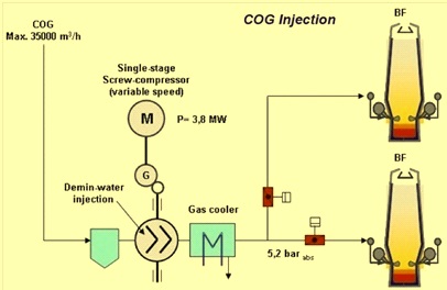
Fig 1 Schematic diagram of COG injection in blast furnace
The injection of COG into the blast furnace is practiced in some countries with different injection rate ranging from about 30 to 280 N cum/tHM. In some blast furnaces, COG is injected only occasionally because of its free availability at the integrated plant is limited. The flexibility of the COG utilization can be enhanced as gas can be moved between the blast furnace and some other user of the available gas, depending on the need at the moment. Thus, the gas injected into the blast furnace substitutes alternative reducing agents that have to be purchased from external sources.
Further, it has been reported that the maximum level of COG injection at the blast furnace tuyere is thought to be 0.1 ton COG/tHM according to the thermo chemical conditions. The coke/COG replacement ratio achieved normally is 0.4-0.45 kg/N Cum (around 0.98 ton of coke/ton of COG) compare to 0.8-0.85 kg/ N cum for natural gas (NG).
A mathematical model has been developed by MEFOS, Sweden for an injection tuyere in a blast furnace to simulate the combustion, when injecting reducing gas. The mathematical modeling on the injection of COG into the blast furnace tuyeres indicated that better combustion conditions and higher injection rate are achieved by using two injection lances compared to one lance. Injection of COG with single lance has resulted in (i) very inhomogeneous view of temperature and velocity, (ii) the flow reaches to the end of the raceway with high velocity, (iii) highest temperatures at the end of the raceway, and (iv) no overheating of the tuyere. Injection of COG with two lances has resulted in (i) significantly decreased penetration depth, (ii) more homogeneous distributions of temperature, velocity and gas concentration, (iii) more uniform combustion similar to heavy oil injection, and (iv) no overheating of the tuyere. Other points related to use of one lance or two lances in a typical blast furnace are given below.
- When using one injection lance, the maximum injecting quantity is 10 000 N cum/h. If the injection amount is higher, part of the gas will not combust in the tuyere but will enter into the blast furnace unburned.
- For two injection lances, the maximum injecting quantity is increased to 15 000 N cum/h, due to better combustion conditions. The conditions are better as the inlet velocity of the gas is lower, the turbulence in the tuyere pipe is enhanced, and also more of the coke oven gas is in contact with the blast, i.e. the reacting area is bigger.
- The effect of varying the injection angles of the lances on the predicted results is not obvious.
An outline of a typical tuyere lance system is shown in Fig 2. It includes two injection lances for COG injection, which are inserted into the blast pipe, a blast pipe and a copper tuyere.
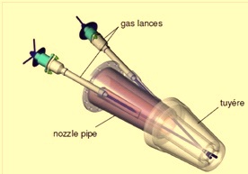
Fig 2 Typical tuyere lance system with two lances.

Leave a Comment