Welding of Carbon and Low Alloy Steels and Hydrogen Induced Cracking
Welding of Carbon and Low Alloy Steels and Hydrogen Induced Cracking
Arc welding is a process by which steels are joined by coalescence. Normally the process uses a compatible filler material. Before a well-bonded joint is produced, the joint surface is to be heated above the melting temperature in order to completely fuse with the weld metal. Though the metallurgical reactions which involve melting, solidification, and solid-state transformation are not unusual, the temperatures and cooling rates observed are severe.
Active gases also are present and can dissolve in the fused steel. Fluxes are introduced to alloy with and protect the weld metal. Generally, joints are rigid and restrain dimensional changes caused by shrinkage and solid-state transformations, producing residual stresses of yield-strength (YS) magnitude. Since the metallurgical changes do not occur under equilibrium conditions, and since the stresses are high, many of the reactions can take place in either or both the weld metal and the heat affected zone (HAZ) of the steel and can produce defects that weaken their soundness.
Because of the tremendous variability of the welding processes, it is difficult to provide much detail about the exact mechanisms involved or the corrections that can be made. Furthermore, many corrective measures are obvious once most defects are explained. One problem, which relates to hydrogen (H2), is not simple. Since this problem is becoming more relevant as more high-strength, low-alloy (HSLA) steels are being welded, the subject of hydrogen-induced cracking (HIC) is very important.
Carbon (C) and low alloy steels are welded since they have widespread application and good weldability. This usefulness is mainly due to the metallurgical characteristics of the iron (Fe) base system. The characteristic includes the ability to undergo allotropic (microstructural) transformation which allows the opportunity for hardening and strengthening through martensitic and bainitic transformations or precipitation mechanism in addition to the ability to be readily alloyed with a large number of elements. The weldability of C and low alloy steels can be generally classified into (i) fabrication weldability and (ii) service weldability.
Fabrication weldability is because of the possibility of joining C and low alloy steels by welding without introducing harmful discontinuities. The acceptability of these discontinuities depends on the application conditions for the specific weldment. The fabrication weldability of steel can be adequate for a noncritical application. However, the same steel may not be suggested for a critical application, or special precautions, such as preheat, may be needed when welding. Fabrication weldability deals mainly with discontinuities such as H2 assisted porosity, lamellar tearing, cold cracking, hot cracking, and reheat cracking.
Service weldability of C and low alloy steels is due to the fact that the finished weldment has properties sufficient to serve the intended function. An important feature of service weldability is the comparison of HAZ properties with those of the unaffected base steel. The acceptability of the service weldability also depends on the planned application. The service weldability of certain steels can be acceptable for an application where corrosion is very important but toughness is of secondary importance. However, the same steel is unacceptable for an application where toughness is very important. Service weldability involves the effect of the welding thermal cycle on the properties in the HAZ. Service weldability frequently determines the range of heat inputs allowable for certain steels. Low heat inputs can introduce undesirable low toughness microstructures, as well as fabrication weldability problems linked with cold cracking. High heat inputs can introduce coarse microstructures with both low toughness and low strength. The heat input alone does not control the resulting microstructure and HAZ properties, but the induced thermal cycle controls the microstructure and properties. Hence, both heat input and thickness of the steel are important.
Classification of steels
The C and low-alloy steels cover a wide variety of compositions and properties. Steels are frequently classified according to their C and/or content of the alloying elements. The different classifications are available under various designations, such as plain C steels, C-Mn (manganese) steels, medium C steels, low alloy steels, high strength low alloy (HSLA) steels, and micro-alloyed steels. Recently, a new classification of steel has introduced the steel processing method as a classification factor. These steels, known by various designations, are frequently described as thermo-mechanical controlled processing (TMCP) steels. The boundaries between all the above classifications are often diffuse, they frequently overlap, and they are sometimes subjective.
Low C steels contain up to around 0.30 % C and up to around 1.65 % Mn. Most of the as-rolled steels used for welded applications consist of low C steel. This group includes steels which can have wide variations in weldability. As an example, it is possible to weld low C steels with less than 0.15 % C by all the welding processes. It is also possible to weld low C steel containing 0.15 % to 0.30 % C (usually known as mild steel) in thicknesses up to 25 mm. However, thicker sections of mild steel may need additional actions for successful welding.
HSLA steel is designed to provide better mechanical properties than those of conventional C steels. This steel normally has YS of 290 to 550 N/sq mm and is of the C-Mn type, with very small additions of niobium (Nb) and vanadium (V) for ensuring grain refinement as well as precipitation hardening. HSLA steel is normally identified as micro-alloyed steel. This steel is normally welded in the as-rolled or the normalized condition. The weldability of the HSLA steel is similar to the weldability of mild steel.
Recently, a new family of HSLA steels with low C, copper (Cu) bearing age-hardening has been developed. These steels are not truly low alloy, since the total content of Cu, Ni (nickel), and Cr (chromium) is usually near 1 %. The weldability of these steels is very good, mainly because of their low C content (less than 0.06 %). These steels are generally being used in the quenched and aged condition. Because of these two conditions, these steels are sometimes are also characterized as TMCP steels. Quenched and tempered (Q&T) steels are heat treated for getting YS of 350 to 1030 N/sq mm. Other examples of these steels include Ni-Cr- Mo (molybdenum) steels. Weldments of these steels generally do not need further heat treatment except for a post weld heat treatment (stress relief) in some special applications. Advantage of these HSLA steels over selected quenched and tempered steels is the reduced welding pre-heat requirement for the Cu age-hardening. However, these HSLA steels do not weld like mild steels.
Heat treatable low alloy (HTLA) steel is normally re-austenitized, then quenched and tempered after welding. This steel is relatively hardenable steel which in its quenched and tempered condition develops YS higher than 960 N/sq mm. Weld metals usually cannot develop acceptable combinations of strength and toughness at this level in the as-welded or stress-relieved condition. Hence, it is necessary to re-austenitized and then to quench and temper the entire weldment after welding.
TMCP steels are generally produced with a combination of controlled rolling followed by accelerated cooling or in-line direct quenching. This processing allows development of a combination of high strength and high toughness while maintaining good weldability. The weldability is good since the content of the alloying elements in these steels can be kept very low, with C content usually less than 0.06 %. YS levels as high as 700 N/sq mm and above are possible with these steels. These steels normally can be welded without preheat. However, at the high strength levels, preheat may be needed in order to prevent cracking in the weld metal.
Cr- Mo steels are widely used for high temperature applications. The Cr content of these steels varies from 0.5 % to 9 %, and the Mo content from 0.5 % to 1.0 %. These steels are generally delivered in the ‘normalized and tempered’ or the ‘quenched and tempered’ condition. Since these steels have reasonable hardenability, adequate precautions are needed to avoid H2 assisted cold cracking (HACC). The service application often imposes additional requirements on the welding of these steels. As an example, in some industry, these steels are needed for their creep resistance, and both the weld metal and HAZ are to provide adequate creep properties. The corrosion atmosphere in some industry requires that the maximum HAZ hardness be limited to avoid corrosion cracking.
Relative susceptibility of steels to HACC
Graville has suggested that the susceptibility to HACC can be evaluated by calculating the C equivalent (CE) and comparing it to the C content as shown in Graville diagram (Fig 1). Steels under zone I have low C and low hardenability and are not very susceptible to cracking. Steels under zone III have both high C and high hardenability, and all welding conditions produce crack-sensitive microstructures. Hence, for avoiding HACC in steels under zone III, it is necessary to use low H2 measures, including preheat and post-weld heat treatments. Steels under zone II have higher C levels with lower hardenability. Hence, it is possible to avoid crack-sensitive microstructures by restricting HAZ cooling rates. This can be accomplished through control of heat input and, to a minor extent, with preheat.
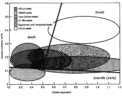 Fig 1 Graville diagram showing susceptibility of steels to HACC relative to C content and CE
The CE considered in Graville diagram is CE = % C + (% Mn + % Si)/6 + (% Ni + % Cu)/15 + (% Cr + % Mo + % V)/5. Susceptibility to cold cracking is progressively increased as steels transfers from zone I to zone II, and to zone III. Graville diagram also shows that heat-treatable alloy steels, mainly in zone III, need special considerations for welding. Cr- Mo and Q&T steels also need care, as needed by some HSLA steels. Low C steels are readily welded except in thick sections, for which some precautions are necessary. The TMCP steels have been specifically developed so as to lie in zone I, and because of it their weldability is excellent. Fig 1 signifies only one aspect of weldability and there are many other concerns, the desired preference with regard to HACC is to use steels that push the compositional cover toward the lower-left corner of the Graville diagram.
Normal defects associated with arc welds
Porosity is caused by the entrapment of small pockets of gas, particularly H2 and N2 (nitrogen), which typically has a higher solubility in liquid, rather than solid, iron (Fe). During solidification, gases attempt to leave the weld metal. However, because of high solidification rates, some gas may get entrapped. This entrapment depends both on the rate of gas dissolution and on the rate of the solidification of the weld metal. If the dissolution rate is high, gas bubbles have a chance to develop and escape before the steel solidifies. If the rate is low then the gas remains in solution, which avoids porosity but allows other problems such as H2 induced cracking (HIC) or poor toughness. At intermediate rates, the gas can nucleate and, depending on the amount of gas dissolved in the weld metal and the weld solidification rate, develops bubbles which get trapped. A very severe form of porosity, called worm holes, occurs when the rates of gas evolution and solidification are same, causing elongated gas pockets to develop in place of essentially spherical bubbles.
Among the possible sources of H2 is moisture in fluxes, hydrocarbons in either wiredrawing lubricants or surface contaminants in the joint to be welded, and water leaks in ‘gas metal arc welding’ (GMAW) equipment. N2 is collected from air which enters the arc regions as a result of poor shielding of the arc. With GMAW, this can happen when the gas flow rate is either so low that cross-drafts displace the shielding or so high that the surrounding atmosphere is aspirated into the shielding gas. With the ‘shielded metal arc welding’ (SMAW) process, this can happen when welders are not adequately skilled or use improper methods which cause the arc length to be excessive.
Incomplete fusion can take a number of forms, such as inadequate joint penetration, absence of root fusion, or lack of side-wall fusion. These defects can be caused by (i) insufficient energy input to the weld, mainly inadequate current, (ii) excessive travel speed, which allows weld metal to flow ahead of the arc, or (iii) improper electrode angle or work position.
Difficulties with joint penetration and root fusion are usually due to the use of a joint design which is not proper for the welding process being used or to a disregard for the measures that are needed to provide adequate penetration of the arc. In most cases, this means that the welding current is too low. However, in the case of the gas-shielded welding processes, it can mean that the wrong shield gas is being used. As an example, with argon (Ar) rich gas mixtures, the penetration pattern is relatively shallow, with the exception of a fairly deep central ‘finger’. Unfortunately, this finger is usually not positioned centrally and, hence, cannot be relied upon. However, shield gas mixtures which are rich in helium (He) or carbon dioxide (CO2) are capable of a more uniform and deeper useful penetration pattern. Poor root fusion which occurs when welding from one side requires either a modification in the joint design to allow better penetration or a change to welding from both sides of the steel piece.
In most cases, the lack of side-wall fusion between the weld metal and the joint occurs when proper measures or controlling techniques are not used by welders. With the GMAW process, it can be due to using inappropriate variations, such as short-circuiting transfer, when welding heavy sections. Short-circuiting transfer is effective only at low energy levels, which makes it very suitable for welding steel sheet or thin plate in all positions. This is because the process is designed to provide little penetration and to quickly freeze weld metal. For that reason, the weld metal is not fused the side walls of joints from which heat is extracted rapidly, that is, those thicker than 6 mm. Both a spray arc with Ar and a buried arc with CO2 shielding deposit welds which are too massive and fluid to be supported in the vertical or overhead positions. However, these processes are very effective for making welds in the flat or horizontal positions. On the other hand, the pulsed arc variation with Ar rich shielding is very effective in all positions, offering both sufficient penetration and control of the weld pool to prevent defects caused by poor side-wall fusion.
Hot cracks are also called centerline or solidification cracks and are caused by the rejection of low melting constituents along the centre line of restrained welds. They develop immediately after welds are completed and, sometimes, while the welds are being made. If the welds are broken to expose these cracks, they are found to be blued, or heat tinted. These cracks, which are often caused by sulphur (S) and phosphorus (P), are more likely to occur in higher C alloy steels. Mostly, the base steel plate is their source. The susceptibility to cracking, based on weld composition, has been compared with empirical equations, such as UCS = 230 X % C + 190 X % S + 75 X % P + 45 X % Nb – 12.3 X % Si – 5.4 X % Mn – 1. In case, the UCS value is less than 10, then the susceptibility to cracking is low, whereas a value higher than 30 means that this susceptibility is high, and a value between 10 and 30 means that the welding techniques need controlling.
Defects, like hot crack and crater cracks in weld bead, are more likely to occur with welding processes or techniques which produce high dilution (that is, deep penetration). Another factor that contributes to centerline cracking is a sharp tear-drop profile of the weld crater, which is characteristic of high welding speeds. In these situations, the weld crater often develops shrinkage cracks, called crater cracks. Both the teardrop crater and deep penetration are produced with the ‘submerged arc welding’ (SAW) process and the GMAW process using CO2 shielding. The problem can also occur in fillet welds which are very concave, since their cross section might not be sufficient to tolerate the transverse stresses which are due to weld shrinkage.
In most cases, the problem can be prevented by keeping the combined S and P levels below 0.06 %. However, when welding highly restrained joints using high strength steels, a combined level below 0.03 % is generally necessary. When the steels to be welded contain excessive amounts of S or P, hot cracks can be avoided by (i) using welding practices or techniques which are not deeply penetrating, (ii) selecting travel speeds which are sufficiently slow to prevent the formation of tear drop craters, (iii) providing convex bead profiles, and (iv) filling the craters at the end of each bead.
Lamellar tearing occurs in the base steel plate when stressed through its thickness and is normally found just below the HAZ. It is associated with banded steels that contain thin layers of inclusions located beneath the steel plate surfaces. If the dirty steel is to be used then the problem can be prevented by changing the joint design to minimize strain through the thickness of the steel plate at the weld.
An undercut is an irregular gouge which is usually found in the upper toe of a horizontal fillet weld. The steel base plate in that section of the weld is melted by the arc, but not refilled by the weld metal. Most often, this defect is caused by improperly selected welding conditions such as the electrode angle, travel speed, and welding current. It is more likely to occur when attempting to make fillet welds with legs which are higher than 8 mm in length. With the GMAW process, it also can occur when using an Ar shield containing less than 2 % oxygen (O2). Undercut also can be found in welds made in the vertical position, where it is generally ascribed to excessive weaving.
An overlap, also called a rollover, is usually associated with fillet welds and can be found when either the welding current is too low to properly fuse the base steel plate or the travel speed is too low to accept the amount of metal being deposited. Poor handling of the electrode during the SMAW process can also be a factor.
Inclusions are produced by slag which is trapped between weld passes. They originate as pieces of un-fused fluxes that may be trapped in a joint, or as slag which is allowed to flow ahead of the arc and is covered by the weld, or as solidified slag which has not been removed between weld passes, or as heavy mill scale which has not been removed from a joint prior to welding. The problem is most common with the SMAW process since it can be intensified by poor controlling techniques on the part of the welder. The presence of inclusions can be anticipated when welding over highly crowned or rough welds since their edges are difficult to clean between passes or to penetrate during welding. Prevention is possible by (i) training welder to deposit weld which has accurate flat profile, (ii) positioning welds to allow higher energy and more fluid deposits to be made, (iii) preventing the development of rust between passes, and (iv) ensuring that the welds are properly conditioned between passes by either cleaning or grinding.
Hydrogen induced cracking
Hydrogen induced cracking (HIC) is a phenomenon mainly associated with welds in low alloy steels. The factors which contribute to HIC are (i) presence of H2, (ii) high tensile stress, (iii) susceptible microstructures, (iv) temperatures which are between around 200 deg C and -100 deg C, and (v) time. At lower strength levels (around 490 N/sq mm) HIC is normally observed as longitudinal cracks in the HAZ of the base steel, often called under-bead cracking. At higher strength levels (around 830 N/sq mm and higher), transverse cracks can occur in the weld metal as well.
The often used expression ‘H2 embrittlement’ suggests that H2 damages the toughness of welds, but the term is a misnomer. Impact tests on material removed from the area between cracks has shown that the material exhibits levels of toughness which is equivalent to welds made in the absence of H2 and, of course, cracks. However, tensile ductility can be reduced because HIC can occur while the tensile test is in progress, which reduces the cross-sectional area of the test sample. The resulting defect in the fractured surface is called ‘fish-eye’. Cold cracking is another expression which has been used to differentiate these cracks from the hot cracks which are found in weld metal and are produced by low-melting constituents that segregate during solidification. Delayed cracking is another term which is being used. It is descriptive because HIC might not occur for days or weeks. When HIC is anticipated, welds are frequently not radiographed for a week or more in order to allow the cracks to develop.
Mechanism
Hydrogen is a universal impurity in all arc welding processes. It exists in the water which cannot be avoided in fluxes, in the organic lubricants on the surfaces of filler wires, in the debris that collects in weld joints, and in the moisture in air that can be aspirated into the arc stream. H2 has a higher solubility in liquid Fe than it has in solid Fe, and its solubility decreases with temperature in the solid Fe as well. The solubility of H2 in Fe is a function of temperature.
The solubility above the liquidus at 1500 deg C is around 30 ppm (parts per million) by weight, but around 8 ppm in the solid state. At 400 deg C, its solubility drops to less than 1 ppm. The rate of weld metal solidification is very high and, as a result, the H2 which has dissolved in the fused weld metal is retained. Although H2 which does escape as gas often is trapped in the form of small bubbles or weld-metal porosity, a substantial amount does remain in the solidified weld metal as supersaturated H2. The residue might appear to be insignificant, but it is to be acknowledged that as little as 1 ppm of H2 can cause cracking problems in high strength steels.
During the cooling interval, the atomic H2 diffuses rapidly, with some going into the weld HAZ, some escaping to the air, and the rest remaining within the weld metal. Given the right conditions, these highly mobile atoms look for rifts and discontinuities in the metal lattice and concentrate at those points. In concert with the residual stresses in the lattice which are due to external restraint and volume changes caused by solidification and solid-state transformation, the H2 enlarges the discontinuities to form micro-cracks. The localized stresses are relieved abruptly as the atoms penetrate the fissures and become trapped as molecules. The resulting micro-cracks, which have sharp tips, are also linked with high stress concentrations at which additional atoms collect. These stresses are build up until they, too, are relieved as the crack is extended. This process of stress build up and relief by cracking continues till (i) the cross sectional area is reduced sufficiently to cause failure, (ii) H2 escapes in a sufficient amount to lower its concentration below the level which is needed for cracking to proceed, and (iii) under bead cracks have reduced the residual stresses in the weld below the level needed for cracking to proceed.
HIC does not occur spontaneously, but as discrete steps. The stepwise progression can be observed acoustically. In small specimens, its progression also can be monitored by measuring changes in resistance. The monitoring depicts the changes in resistance that occur after the process of HIC begins, as well as the way in which HIC progresses a step at a time until failure. The monitoring also shows the sensitivity of HIC to the level of external stress. Failure occurs quickly when the stress on a specimen exceeds its tensile strength (TS), whether or not H2 is present. However, when enough H2 is present, damage that is caused by HIC can be initiated with stresses well below the TS. With enough H2 and time, HIC can cause failure. Normally the time needed for initiating the cracks and leading to failure increases as the stress is reduced.
It is important to know that HIC does not occur below a critical stress. In addition to the applied stress, the amount of H2 dissolved in the steel also plays an important role. With increasing H2, less stress is needed to initiate HIC, and the time needed for its initiation is reduced, as well. The interaction of these two variables, stress and H2 shows that both the time to initiate HIC and the critical stress below which failure does not occur are inversely proportional to the amount of H2 present in the steel.
The third variable which affects HIC is the microstructure of the steel (either the weld metal or the HAZ). Twinned martensite, which occur in steels with higher C content (more than around 0.3 % C), are usually very difficult, although the problem can occur with all acicular microstructures, including the bainite. This supposition might be defective since the acicular microstructures are typical of those associated with high strength steels, and higher stresses, in themselves, are an aggravating factor with HIC. However, steel with a relatively tolerant microstructure can show a higher critical stress than stronger steel with a sensitive microstructure. Normally the stronger steel is more sensitive to H2 with regard to both an earlier initiation time for HIC and a lower critical stress. Such behavioural differences have been observed between high strength martensitic and weaker bainitic steels.
Inclusions also are important. The toughness of HSLA steels is impaired by impurities, particularly when in the form of inclusions. However, since inclusions can serve as sinks for H2 atoms, they also can have a beneficial effect. For this reason, some very high purity steels have been shown to be surprisingly sensitive to HIC. It is not to be concluded that welds need to be stressed externally in order to develop HIC. The differential shrinkage associated with fusion welding always produces residual stresses in weldments, and, with rare exceptions, those stresses are at least equivalent to the YS of the weakest component of the joint. Since most weld metals are stronger than the base steel, the residual stresses are close to the YS of the base steel plate. Frequently, it is possible to minimize the development of HIC in critical structures by selecting a weaker, or under matching, weld metal to keep the residual stresses as low as possible. With some applications, such as those involving fatigue, a weaker but sound structure can be more suitable than one that contains HIC. However, given a sensitive microstructure and enough H2, the critical stress can be very low, which is substantially less than typical residual stresses. Therefore, if HIC is a problem, it develops, in most cases, before a welded structure leaves the fabrication area.
Another important observation is that the mechanism of HIC is affected by temperature. The chances for HIC are minimal when temperatures exceed around 200 deg C. At higher temperatures, the H2 diffusion rate is very high to allow the atoms to concentrate at lattice defects or other sharp discontinuities in the weld. Since the mobility of H2 is essentially nil, HIC is unlikely to occur in welds cooled below -130 deg C.
Control of HIC
While considering the metallurgical requirements for HIC, it is obvious that a number of approaches can be adopted to avoid its occurrence. These requirements include reduction of the residual stresses connected with a weldment. These are (i) avoidance of acicular microstructures in the weld metal and HAZ or at least selecting those microstructures which are bainitic, rather than martensitic, (ii) reduction of the amount of H2 dissolved in the weld metal during the welding operation, or (iii) allowing H2 to escape before it can cause damage. The most suitable of these approaches depends on the size of the component to be welded, the mechanical properties needed, the service foreseen, the welding process to be used, and the cost limitations. In most cases, compromises need to be made and a combination of these approaches is possibly most cost effective.
As stated earlier, the residual stresses in welds are usually equivalent to the YS of the weakest material in the joint. In joint configuration which introduces high tri-axial stress, the residual stress can be significantly higher than the YS. Although designer rarely uses weaker materials just to reduce residual stresses, It is to be recognized that HIC can have a significant effect on the fatigue life of a structure. To accommodate weaker steel, a more acceptable compromise can be to redesign the weldment to incorporate thicker sections. However, other approaches can be taken to take full advantage of the strength available in low alloy steel without incurring HIC.
Since the changing of the microstructure of the weld metal or the HAZ is a remote possibility, unless there is the option of selecting different steel, the steel material which is most tolerant of HIC is to be selected. Another method for reducing the residual stresses in the weld is to use a post-weld heat treatment at temperature which is less than the critical temperature. Since the steel is weaker at higher temperature, a substantial reduction of residual stress is possible by heating the weld to a temperature at which plastic yielding can occur. For steel with a tempered martensite structure, the most suitable choice for this heat treatment would be at or just below its original tempering temperature, which is generally close to 620 deg C. This treatment is called stress relief annealing (SRA). For this treatment to be effective, the weldment is to be kept in a suitably large furnace before its temperature drops below 200 deg C and then, to prevent difficulties related with distortion, heated and cooled slowly. Considering the temperature and time required for the SRA treatment, it is obvious that all of the diffusible H2 in the weld will escape. However, unless the stresses in a weld are to be relieved for reasons other than the avoidance of HIC, SRA can prove to be a very costly option. Post-heating also has a place in the scheme of preventing HIC. It is not necessary to reheat weldment to temperatures which are much higher than 200 deg C in order to accelerate the escape of H2 and still avoid the temperature range within which HIC is likely to occur. Such thermal treatments are good for welded components which are small enough to be preheated in a furnace prior to welding and returned to the furnace immediately after welding for a period of time which allows all of the H2 to escape. This approach is mainly important for very high strength alloy steel, which is very sensitive to cracking problem connected with H2.
Similar result is possible by slowing the rate at which weld is allowed to cool after welding. This provides more time for H2 to escape before temperatures drops below 200 deg C. Retarding the cooling rate also allows the transformation of austenite to softer microstructures that are less sensitive to HIC.
The cooling rate of arc welds is affected mainly by three factors namely (i) the temperature of the joint before welding begins, (ii) the arc energy input during welding, and (iii) the joint thickness. The initial temperature can be the ambient temperature of the area where the steel has been stored, or the temperature to which the weldment has been heated as the result of a previous weld by external methods (the inter-pass temperature), or the temperature to which the joint had been heated (the preheat temperature). As preheat temperature is increased, the cooling rate decreases. The arc energy input is defined by the electrical energy dissipated by the arc and the speed at which the arc is moved along the joint. Higher arc energy input retards the cooling rate.
The joint thickness also affects cooling rate since most of the heat entering the joint is extracted by conduction into the body of the weldment. Conduction is at a maximum with three-dimensional cooling. This occurs when the joint is thicker than around 25 mm. Conduction is less effective in thinner sections, which means that the weld cooling rate is inversely proportional to the thickness. Though the cooling rate of thin section is also influenced by radiation and convection, the effect is much less pronounced than that of conduction.
The variables described above can be incorporated into a single equation which allows calculations to be made of the rate at which weld cools at a specific temperature. CRt = K [(T-To)2 /E] where CRt is the cooling rate at temperature T, K is a constant of proportionality (including an adjustment for the steel thickness, if it is thinner than 25 mm), To is the preheat or inter-pass temperature, and E is the arc energy input, which is calculated as E= VI/S where V is the arc voltage, I is the welding current, and S is the arc travel speed. By combining the above two equations, a general expression for cooling rate is obtained which is CRt= K [(T-To)2*S/VI]. This equation has been developed for the purpose of predicting weld and HAZ microstructure in conjunction with continuous-cooling transformation diagram. This diagram allows the determination of the cooling rates above which strong martensite or bainite are ensured or below which they can be avoided. The same equation can be used to calculate the cooling rate at temperature critical to the evolution of H2 and the avoidance of HIC.
The adjustment of welding procedures is accomplished by varying the current or the travel speed. Voltage is a strongly dependent variable which is determined by (i) the welding process, (ii) the characteristics of the electrodes, fluxes, or shielding gases, and (iii) the current. It is not to be viewed as a variable with which to control weld cooling rate.
The other method of retarding cooling rate, which is possibly the most common method, is to control the preheat temperature or inter-pass temperature of the joint prior to welding. Relatively small changes in these temperatures can exert strong effect on cooling rate at temperature around 200 deg C, which is critical with regard to the onset of HIC. As an example, by increasing the preheat temperature from 20 deg C to 100 deg C, the cooling rate at 200 deg C is reduced by around one third. By preheating to 150 deg C, the cooling rate is reduced by a factor of around ten, which is a very significant amount when fabricating high strength steel which has little tolerance to HIC.
Preheating is rather costly. It can affect the weld microstructure and can make working conditions intolerable for the welder. However, preheating is vital for reducing HIC. Preheat affects the lower critical stress in the HAZ of high strength steel when welded with a covered electrode. The ultimate TS of this high strength steel is around 750 N/sq mm. Yet, with a 25 deg C preheat which is the room temperature; failure is caused by HIC in less than 10 min at a stress level of around 490 N/sq mm. The lower critical stress below which failure does not occur is around 415 N/sq mm. By preheating to a temperature of 120 deg C, the critical stress is increased to 620 N/sq mm, which is around the YS of the high strength steel, but still considered unsafe. To avoid HIC entirely, under the conditions used to produce the weld, the preheat temperature need to be higher than 150 deg C.
A number of approaches have been used to select the most appropriate temperature for preheating steel for the avoidance of HIC. Some approaches rely on empirically derived tables which list the steels and recommended welding measures, including those for preheat and post-heat. Another relates cracking tendencies quantitatively to the hardenability of the steel, calculating it on the basis of the CE. One such formula for CE is given by the equation CE = C + Mn/6 + Si/24 + Ni/40 + Cr/5 + Mo/4.
For application which involves weld to be made with covered electrode, the recommended preheat temperature for steels having different CEs although show a considerable scatter, yet the overall trend demonstrates a linear relationship between the CE and the preheat temperature. For a quick approximation of the required preheat, the relationship To =200 CE can be used, where To is in deg C. For including the scatter band which incorporates all of the data points, a more-precise interaction between the CE and the preheat temperature can be shown by relationship To = 210 CE (+15 to -45). The scatter band of 60 deg C is quite large, which suggests that the upper portion be used for selecting suitable preheat temperatures with which to avoid potential problems. However, if metallurgical softening needs to be avoided, then the most appropriate course of action is to rely on laboratory trials for determining the minimum effective level of preheat. Of course, such a determination needs that the energy input, the thickness of the joint, and the welding process is also to be considered.
Measurement of H2
Direct measurement of H2 in weld metal is difficult. Unless good care is taken to stop its escape from a weld before an analysis can be made, the amount measured is not generally the representative of that which might have caused a crack to develop. This means that sample is to be planned to be analyzed quickly or super-cooled in liquid nitrogen (N2) to stop the diffusion of H2 while awaiting analysis. The technique recommended by the American Welding Society (AWS) measures the volume of H2 gas which escapes from a test weld which is around 75 mm long. It is collected in either a eudiometer tube (in a mercury or glycerine bath) or in the isolation chamber of a gas chromatograph.
Indirect methods also have been used by measuring the sources of the H2. For wires used in the GMAW and SAW processes, this can be done by measuring the hydrocarbons on their surface. Mass spectrometry can be used for the analysis. For the SMAW and SAW processes, the moisture adsorbed in the fluxes can be determined. Often, this is done by measuring weight loss after drying at high temperatures of around 400 deg C to 425 deg C. The issue related with indirect measurements is that the efficiency of transfer of the H2 to the weld from the wires or fluxes is difficult to predict. It is normally dependent on the welding technique. Hence, empirical results are used to relate the amount of H2 present in the welding materials to the HIC in the weldment. For this reason, a comparison among processes becomes very difficult. However, even the measurements of gas evolution can be faulted, since only the diffusible H2 is measured. Some remains in solution and some are trapped within weld defects or inclusions.
Importance of welding process
The arc welding process needs a source of filler material and methods for protecting and controlling the arc and the deposited metal. In most of the cases, the filler material is provided in the form of rods, continuous wires, or continuous tubes. The surface of all of these materials is contaminated with residue of H2 rich drawing lubricant. In the GMAW process, a shield gas is used for protection. For cored wire, a combination of shield gases and fluxes are used. The submerged arc and covered electrode techniques involve only fluxes. All of the fluxes are sources of chemically combined or adsorbed water. The quantity of H2 dissolved in weld metal can vary, not only between but within processes.
Of all of the arc welding processes using consumable electrode, the GMAW process is associated with the lowest H2 levels, the primary source being residual drawing lubricant on the wire surface. Totally dry wire is unacceptable, because it is difficult to feed. The amount of residual lubricant generally is not a problem with steel having YS less than 520 N/sq mm. However, as the YS approaches 620 N/sq mm, the residual lubricant becomes a potentially important factor if HIC is to be avoided, unless relatively high preheat temperature can be used. When the YS exceeds 830 N/sq mm, the residual lubricant is to be kept as low as possible.
The importance of the residues is reflected by the effects of H2 on HIC in welds which have YS of 930 N/sq mm and which need to be minimized by controlling the cooling rate. In this case, the cooling rate is determined at 540 deg C, a temperature close to that at which the weld metal transforms from austenite to martensite. At the relatively rapid cooling rate of around 30 deg C/second, 4 ppm of H2 on the wire surface is shown to have caused HIC. To be securely free of HIC, the H2 is to be maintained at level below 3 ppm. By adjusting the welding technique, preheat temperature, or both, in order to retard the cooling rate at 540 deg C to less than 20 deg C/second, the tolerance for H2 on the wire can be increased to 5 ppm.
As stated under H2 measurements, it is difficult to predict the amount of H2 which gets transferred to a weld from surface contaminants that are decomposed in the arc (or before reaching the arc), mainly when the level is measured in single digit ppm. This level is so low as to prevent the use of gas evolution technique for the measurement of the H2. The higher tolerance for wire surface contaminants at lower cooling rate can be due as much to the softer microstructure as it is to the escape of H2. To retain high strength, the higher cooling rate is necessary. Usually there is a very sudden drop in strength as the cooling rate drops below 10 deg C/second. Obviously, to obtain the strongest possible weld without encountering HIC, it is necessary to minimize the presence of any contaminants that contain H2.
The achievement of very low level of H2 is not possible with any of the other arc welding processes, because they need fluxes instead of shield gases for protection. Fluxes can absorb water. There is the importance of moisture in a submerged arc flux on the cracking sensitivity of a weld metal which has YS of 830 N/sq mm. It shows that diffusible H2 level as low as 7 milli-litres/100 grams can drop the critical strength to 105 N/sq mm (H2 content of 1 ppm is equivalent to 1.11 milli- litres/100 grams). Even baking the flux to reduce the weld-diffusible H2 below 2 milli-litres/100 grams does not eliminate HIC. The critical stress remains below 415 N/sq mm. It is obvious that the welding conditions used for the submerged arc weld are not acceptable. Either the steel is unusually sensitive to H2 or the flux used is not capable of being dried sufficiently to reduce H2 contamination.
Similar HIC problem is encountered in the SMAW process when weld strength exceeds 480 N/sq mm. For this reason, low H2 electrode has been developed specifically to minimize, if not prevent, the problem. Low H2 electrode coating is formulated without any organic material. This low H2 coating is baked at temperature exceeding 430 deg C to reduce residual moisture to a level of around 0.1 %. This is nearly the lowest practicable level, since the absence of moisture in a coating tends to make it brittle. The effect of baking on the residual moisture during initial manufacture shows that even with careful control of formulation and baking, the moisture level of covered electrode coating cannot be reduced to levels sufficiently low to prevent HIC in steel having YS higher than 830 N/sq mm.
The moisture in low H2 electrodes usually is specified as 0.2 % max. This moisture level is what is expected to be found in coatings of commercial low H2 electrodes, immediately after being removed from hermetically sealed containers. However, if exposed to humid, warm air, thee electrode coating reabsorbs moisture. The rate of moisture pickup depends on the constituents in the coating. In some cases, reabsorbed moisture can reach levels exceeding 1 %. For this reason, electrodes are to be stored in heated ovens on hot and humid days and exposed to shop atmospheres only for short times.
Moisture-resistant coating has been developed to counter the reabsorption problem. Although the coating is quite safe when exposed to the relatively cool and moderately humid atmosphere indicated, extra precaution is necessary when welding in tropical conditions. It is possible to salvage electrodes which have become ‘wet’ by re-baking them at temperatures which approach those used during their manufacture. Drying time of around 1 hour is typically needed to recondition electrodes at around 400 deg C to 425 deg C. Although re-baking can salvage electrodes which are inadvertently exposed to moist conditions, the process is not to be repeated since the covered electrodes are alloyed with metal powders which can be oxidized during re-baking operations. Hence, the resulting alloys are leaner and weaker.
Re-baking causes a loss in both Mn and Si content of the weld metal, resulting in a drop in the weld YS. This happens with very controlled re-baking. Unfortunately, the same care is not always taken in shop atmospheres. Significantly greater losses in the Mn and Si contents, as well as mechanical properties, can be expected.
Leave a Comment