Understanding Electric Arc Furnace Steel Making Operations
Understanding Electric Arc Furnace Steel Making Operations
Electric arc furnace (EAF) steel making technology is more than hundred years old. Though De Laval had patented an electric furnace for the melting and refining of iron in 1892 and Heroult had demonstrated electric arc melting of ferro alloys between 1888 and 1892, the first industrial EAF for steel making only came into operation in 1900. Development was rapid and there was a tenfold increase in production from 1910 to 1920, with over 500,000 tons being produced in 1920, though this represented still only a very small percentage of the global production of steel of that time. Initially, EAF steelmaking was developed for producing special grades of steels using solid forms of feed such as scrap and ferro alloys. Solid material were firstly melted through direct arc melting, refined through the addition of the appropriate fluxes and tapped for further processing. Fig 1 shows a typical plan and section view of an EAF
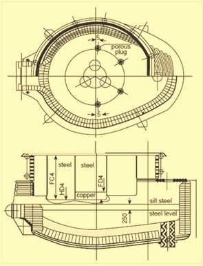
Fig 1 Typical plan and section view of an EAF
Electric arc furnaces range in capacity from a few tons to as many as 400 tons, and a steel melting shop can have a single furnace or up to three or four. In brief, these furnaces melt steel by applying an AC current to a steel scrap charge by mean of graphite electrodes. It requires a tremendous quantity of electricity. The melting process involves the use of large quantities of energy in a short time and in some instances the process has caused disturbances in power grids. These disturbances have usually been characterized as ‘flicker’ (brief irregularities in voltage a fraction of the 50 -60 Hz cycle in length), and ‘harmonics’ (irregularities that tend to occur in a pattern repetitive to the 50-60 Hz cycle). Until only around thirty to thirty five years back, tap to tap times of over three hours were quite common and specific power usage was often well over 700 kWh/ton, nearly twice the thermodynamic requirement (350-370 kWh/ton).
The EAF operates as a batch melting process producing batches of liquid steel. EAF operating cycle is called tap to tap cycle or a heat and is made up of the components namely (i) charging of the furnace, (ii) melting phase, (iii) refining phase, (iv) deslagging operation, (v) tapping of liquid steel, and furnace turnaround.
Tap to tap time is normally less than 60 minutes in modern EAFs. Some twin shell furnace operations are achieving tap to tap times of 35 to 40 minutes.
Charging of the furnace
The initial step in the production of a heat in an EAF is to select the grade of steel to be made. Scrap bucket in the scrap yard is prepared to fulfill the requirement of the specification of this grade. Preparation of the scrap bucket for the charging is an important operation, not only for ensuring proper melt in chemistry but also ensuring good melting conditions. The scrap must be layered in the bucket according to size and density to promote the rapid formation of a liquid pool of steel in the hearth while providing protection for the sidewalls and roof from the radiation of the electric arc. Other considerations include minimization of scrap cave ins which can break electrodes and ensuring that large heavy pieces of scrap do not lie directly in front of burner ports which results into the blow back of the flame onto the water cooled panels.
The charge can include lime and carbon or these can be injected into the furnace during the heat. In many places the practice is to add some lime and carbon in the scrap bucket and supplement it with injection of these materials.
A new heat in an EAF begins with the charging of the scrap. The roof and electrodes are raised and are swung to the side of the furnace so that the charging crane can move and place a full bucket of scrap over the furnace. The bucket bottom is normally of a clam shell design. The bucket opens up by retracting two segments on the bottom of the bucket and the scrap falls into the furnace. The charging crane removes the scrap bucket and the roof and electrodes are swung back into place over the furnace.
The number of charge buckets of scrap needed to produce a heat of steel is dependent mainly on the scrap density and the volume of the furnace. Modern furnaces are designed to operate with a minimum of back-charges. This is advantageous since the charging time is a dead time (furnace with no power-on and hence not melting). Minimizing of the dead time helps in maximizing the productivity of the EAF. In addition, around 10 -20 kWh/ton of energy is lost every time the furnace roof is opened. In many furnaces 2 to 3 buckets of scrap per heat is aimed by the blending of the scrap to meet this requirement. Some operations achieve a single bucket charge. In the case of DRI (direct reduced iron) or HBI (hot briquetted iron), continuous charging with the help of a hopper is usually done. Continuous charging operation with scrap can are also be achieved through ‘Consteel’ or the shaft furnace.
Melting phase
After the charging of the EAF, the roof and then the electrodes are lowered to strike an arc on the scrap. This commences the melting phase of the heat. The melting phase is the heart of EAF operation.
An EAF is a highly efficient melting equipment and the modern designs are based on the maximization of its melting capacity. Melting is carried out by supplying energy to the furnace interior. This energy can be electrical or chemical. Electrical energy is supplied through the graphite electrodes and normally has a very large contribution in the melting phase. Initially, an intermediate voltage tap is selected until the electrodes bore into the scrap. Usually, light scrap is placed on top of the charge to accelerate bore-in. Around 15 % of the scrap is melted during the initial period of bore-in which consists of a few minutes. After this, the electrodes penetrate the scrap sufficiently and then a long arc (high voltage) tap is used without fear of radiation damage to the roof. The long arc maximizes the transfer of power to the scrap and a liquid pool of steel is formed in the furnace hearth.
At the start of this phase, the arc is erratic and unstable. Wide swings in current are observed which are accompanied by rapid movement of the electrodes. As the furnace environment heats up, the arc stabilizes. Once the molten pool is formed, the arc becomes quite stable and the average power input increases.
Chemical energy is supplied through many sources which include oxy-fuel burners and oxygen lances. Oxy-fuel burners burn fuel gas using oxygen (O2) or oxygen enriched air. Heat is transferred to the scrap by flame radiation and convection by the hot products of combustion. Heat is transferred within the scrap by conduction. Bigger pieces of scrap take longer to melt into the bath than the smaller pieces. In some cases, O2 is injected via a consumable pipe lance to cut the bigger pieces of the scrap.
Once a molten pool is generated in the furnace, O2 is usually lanced directly into the molten bath. This O2 reacts with several elements in the bath such as aluminum (Al), silicon (Si), manganese (Mn), phosphorus (P), carbon (C) , and iron (Fe) etc. These reactions are exothermic in nature and supply additional energy thus helping in the melting of the scrap. The metallic oxides that are formed go into the slag. The reaction of O2 with C in the bath produces carbon monoxide (CO), which either burns in the furnace if there is sufficient O2, and/or is exhausted through the direct evacuation system where it is burned and conveyed to the pollution control system. O2 lancing is also carried out at the end of meltdown to bring down the bath C level to the desired level at the time of tapping.
After enough scrap has been melted to accommodate the second charge, the charging process is repeated. Once the final scrap charge is melted, the furnace sidewalls are exposed to intense radiation from the electric arc. As a result, the voltage is to be reduced. Alternatively, creation of a foamy slag allows the arc to be buried and this protects the furnace shell. In addition, a large amount of energy is retained in the slag and is transferred to the bath resulting into improvement in the energy efficiency of the EAF.
Once the final scrap charge is fully melted, flat bath conditions are reached. At this point, usually bath temperature and bath sample is taken. The analysis of the bath chemistry allows the furnace operator to determine the amount of O2 needed to be blown during refining. At this point, the operator also starts making arrangement for the additions of the ferro alloys at tapping. The quantities are finalized after the refining period.
Refining phase
In the refining phase, the removal of Al, Si, Mn, C, P and sulphur (S) from the steel is carried out. Refining operation is carried out following the melting phase after the flat bath conditions are achieved.
The refining reactions are dependent on the availability of O2. The elements, which are to be removed during refining, have a higher affinity for O2 than the affinity of the C for O2. Thus the O2 preferentially reacts with these elements to form oxides which float out and go into the slag. In a modern EAF, which is operating with a hot heel of liquid steel and slag retained from the previous heat, O2 is blown into the bath almost entire period of the heat. As a result, some of the melting and refining operations occur simultaneously.
Higher level of P and S in the furnace charge than what is required in the in steel as per the specification, are to be removed. Normally the conditions favorable for removal of P are the opposite of those necessary for the removal of S. Hence once these elements go into the slag phase, can revert back into the steel.
P retention in the slag depends on the bath temperature, slag basicity and FeO levels in the slag. At higher temperature or low FeO levels, P reverts from the slag back into the bath. P removal is usually carried out in the heat as early as possible. Hot heel practice is very beneficial for the removal of P because O2 can be lanced into the bath while its temperature is quite low. In the beginning of heat, the slag also contains high FeO level which is carried over from the previous heat thus aids in the removal of P. High slag basicity (CaO/SiO2 ratio) is also beneficial for the removal of P but care is needed not to saturate the slag with lime. This can lead to an increase in slag viscosity, which in turn makes the slag less effective. Sometimes fluorspar (CaF2) is added to help fluidize the slag. Stirring the bath with inert gas is also beneficial because it renews the slag/metal interface thus improving the reaction kinetics. In general, if low P level is a requirement for a particular steel grade, the scrap is selected to give a low level at melt-in. The partition of P in the slag to P in the bath ranges usually from 5 to 15. Generally P is reduced by 20 % to 50 % in the EAF.
Sulphur is removed mainly as a sulphide dissolved in the slag. S partition between the slag and metal is dependent on slag chemistry and is favored at low steel oxidation levels. Removal of S in the EAF is difficult especially in the modern practice where the oxidation level of the bath is quite high. Generally the partition ratio is between 3 to 5 in EAF operations. Usually it is more effective to carry out desulfurization during the reducing phase of steel making. This means that desulfurization is performed just before tapping (where a calcium aluminate slag is built) and during ladle furnace operations. For reducing conditions where the bath has a much lower O2 activity, distribution ratios for S of between 20 and 100 can be achieved.
Control of the metallic constituents in the bath is important for meeting the specification requirement of the steel. Usually, EAF operator aims these constituents at lower levels in the bath than those specified for the final product. O2 reacts with Al, Si and Mn to form metallic oxides, which are constituents of the slag. These metallics tend to react with O2 before the C. They also react with FeO resulting in a recovery of Fe units in the bath. An example is shown in the following equation.
Mn + FeO = MnO + Fe
Mn is typically reduced to a level of about 0.06 % in the bath.
The reaction of C with O2 in the bath to produce CO is important as it supplies a less expensive form of energy to the bath, and performs several important refining reactions. In a modern EAF, the combination of O2 with C can supply around 30 % to 40 % of the net heat input to the furnace. Evolution of CO is very important for slag foaming. Coupled with a basic slag, CO bubbles are trapped in the slag causing it to foam and helping to bury the electric arc. This gives greatly improved thermal efficiency and allows the furnace to operate at high arc voltages even after a flat bath has been achieved.
Dissolved gases, especially hydrogen (H2) and nitrogen (N2), is a concern for steel makers. Burying of the arc also helps to prevent N2 from being exposed to the arc where it can dissociate and enter into the steel. If the CO is evolved within the steel bath, it helps to strip N2 and H2 from the steel. N2 levels in steel as low as 50 ppm can be achieved in the furnace prior to tapping. Bottom tapping is beneficial for maintaining low N2 levels because tapping is fast and a tight tap stream is maintained. A high O2 potential in the steel is beneficial for low N2 levels and the heat should be tapped open as opposed to killing the heat. At 1600 deg C, the maximum solubility of N2 in pure Fe is 450 ppm. Typically, the N2 levels in the steel at tapping ranges around 80 to 100 ppm. Decarburization is also beneficial for the removal of H2. It has been shown that decarburizing at a rate of 1 % per hour can lower H2 levels in the steel from 8 ppm down to 2 ppm in 10 minutes.
At the end of refining, bath temperature measurement and bath sample are taken. If the temperature is too low, power can be applied to the bath. Low temperature is not a big issue in modern steel melting shops where temperature adjustment is carried out in the ladle furnace.
Deslagging operation
Deslagging operation is carried out to remove impurities in the form of slag from the furnace. During melting and refining operations, some of the undesirable elements in the bath are oxidized and enter into the slag. It is advantageous to remove as much P into the slag as early in the heat as possible. The furnace is tilted backwards and slag is poured out of the furnace through the slag door. Removal of the slag eliminates the possibility of P reversion.
During slag foaming operations, C is injected into the slag where it reduces FeO to metallic Fe and in the process produce CO which helps foam the slag. If the high P slag has not been removed prior to this step of the operation, P reversion generally occurs. During slag foaming, slag may overflow the sill level in the EAF and flow out of the slag door.
The typical composition of EAF slag is CaO -45 % to 58 %, SiO2 – 5 % to 15 %, FeO- 10 % to 28 %, MgO 5% to 8%, and MnO – 2 % to 5 %.Besides it also contains CaF2, S, and P.
Tapping of liquid steel
Once the desired steel composition and temperature have been achieved in the furnace, the tap hole is opened, the furnace is tilted, and the steel is poured into a teeming ladle for transfer to the secondary steel making unit. During the tapping process, ferro alloy additions are made based on the bath analysis and the desired steel grade. Deoxidizing agent are added to the steel to lower the O2 content prior to further processing. Common deoxidizers are Al, ferrosilicon and silico manganese. While making C steel heats a minimum of slag carry over is aimed. A new slag cover is built during tapping. For ladle furnace operations, a calcium aluminate slag is a good choice for the control of S. Slag forming compounds are added in the ladle at tapping so that a slag cover is formed prior to transfer to the ladle furnace.
Furnace turnaround
Furnace turnaround is the period between the completion of tapping and the furnace is ready for charging for the next heat. During this period, the electrodes and roof are raised and the furnace lining is inspected for refractory damage. If necessary, repairs are made to the hearth, slag line, tap hole and spout. In the case of a furnace with bottom tapping, the tap hole is filled with sand. Repairs to the furnace are made using monolithic refractories of gunning mixes. The increased use of water cooled panels in the EAFs has reduced the amount of patching or fettling requirement between the heats. In many steel melting shops, the furnace bottom is replaced with a spare bottom on a regular basis (2 to 6 weeks). The hearth maintenance of the replaced bottom is carried out off-line. This reduces the power off time for the EAF and maximizes furnace productivity. Furnace turnaround time is normally the largest dead time (power off) period in the tap to tap cycle. With advances in furnace practices this has been reduced from 20 minutes to less than 5 minutes in some recently installed furnaces.
Heat balance of an EAF
It takes a theoretical minimum of 300 kWh/ton for melting of the steel scrap. To provide superheat above the melting point of 1520 deg C requires additional energy and for typical tap temperature requirements, the total theoretical energy required usually lies in the range of 350 to 370 kWh/ton. However, EAF steelmaking efficiency ranges between 51 % to 64 % and as a result the total equivalent energy input is usually in the range of 550 to 700 kWh/ton in the modern furnaces. This energy can be supplied as electrical energy, through oxy-fuel burners from a variety of fuel sources, and by chemical reactions. The energy distribution is highly dependent on local material and consumable costs and is unique to the specific melting shop operation. A typical heat balance diagram of the EAF is at Fig 2.
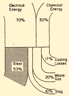
Fig 2 Typical heat balance diagram for an EAF
The energy consumption is highly dependent on the individual operation and vary considerably from one shop to other shop. Factors such as raw material composition, power input rates and operating practices (e.g. post-combustion, scrap preheating) can greatly influence the energy balance. In EAF operation utilizing a large amount of charge carbon or high carbon feed materials, up to 60 % of the energy contained in the off gas may be calorific due to large quantities of un-combusted carbon monoxide. Recovery of this energy in the EAF can increase energy input by 8 to 10 %. Thus it is important to consider such factors when evaluating the energy balance for a given furnace operation.
Leave a Comment