Secondary Cooling Technology in Continuous Casting Process
Secondary Cooling Technology in Continuous Casting Process
A wide range of steel grades ranging from ultra low carbon (ULC) and low carbon grades to high carbon and different grades of special steels are required to be cast in continuous casting machine (CCM). The casting of these grades is to be achieved while maximizing CCM output. Consistent production of prime quality cast steel product requires increased operational and maintenance flexibility in the CCM for maintaining optimum casting parameters can be maintained. This flexibility is needed both for every element as well as control system of CCM.
While the strand is continuously withdrawn at the casting speed, solidification of steel continues beneath the mould through the different zones of cooling having a series of water sprays. The secondary cooling system consists of these different zones, each responsible for a segment of controlled cooling of the solidifying strand as it progresses through the CCM. The sprayed medium is either water or a combination of air and water (mist spray cooling). Mist spray cooling provides the following advantages.
- Uniform cooling
- Less water requirement
- Reduced surface cracking
Product quality in a CCM is considerably influenced by temperature variations during strand cooling in secondary cooling zone. Hence secondary cooling zone has a very important function for the maintenance of a correct temperature parameter and is crucial to the quality of the cast steel product.
Since the quality of steel depends on the behavior of the surface temperature and the solidification of steel front in time, it is to a large extent defined by the intensity of the water sprays. Improper cooling conditions can have detrimental impact on stress distribution in solidified shell. First of all, overcooling can lead to the formation of cracks. Moreover, there must be a smooth transition of the surface temperature as the steel passes through in the secondary cooling zone. In addition, under cooling of the strand during secondary cooling can result in a liquid pool that is too long. These technological requirements demand more efficient and reliable spray cooling and result in constraints that must be imposed on the secondary cooling process. The spray flow rates are normally adjusted to control the strand surface temperature until the molten core is solid enough to reach the metallurgical length.
The two mechanisms of overcooling and under cooling also lead to midway cracks and surface cracks respectively. If such quality problems are encountered in a casting operation, a rational basis is required for changing the settings in the secondary cooling zone, to yield a more satisfactory surface temperature profile.
A schematic diagram of a CCM showing secondary cooling zone along with water sprays is at Fig 1
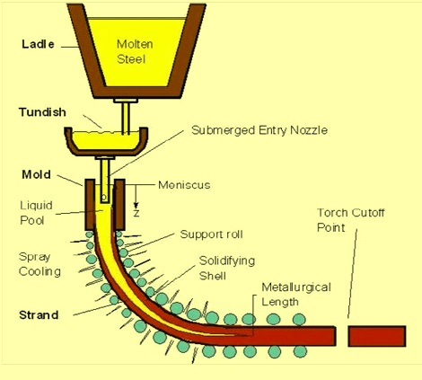
Fig 1 Schematic diagram of secondary cooling zone showing water sprays
Design aspects of secondary cooling zone
Solidification behaviour in CCM technology arises from the dynamic nature of the casting process. In particular it relates to the following issues.
- Handling of very high heat flux in the mould
- Nurturing of the initial thin and fragile solid shell for avoidance of breakout during descent of the strand down the mould
- Designing of casting parameters in tune with the solidification dynamics of the steel grade for minimization or elimination of surface and internal defects in the cast product.
It is important to design a uniform cooling system to control the temperature of the partially solidified cast. The important concerns when designing a secondary cooling system are as follows.
- Steel grades to be cast and their casting speeds
- The roll support geometry and machine segment layout
- Ease of maintenance.
- Secondary cooling control systems.
In the present day CCMs, the design of a secondary cooling system normally uses the latest nozzle technology to fulfill the stringent operational and production requirements of the casters. The layout of the secondary spray cooling system is one of the first steps which need careful considerations when a new continuous casting machine is designed. In secondary cooling, number of nozzles is distributed over the surface of the moving strand. Overlapping of sprays may occur and hence distance between nozzles is important.
It is essential that nozzle arrangements produce an even heat removal across the strand while maintaining a stable spray pattern. Spray collision with support rolls should be avoided as this will result in inefficient use of spray water and a reduction in heat transfer. Generally multi nozzle layouts should be the preferred arrangement.
The staggering of nozzle pairs in consecutive roll gaps ensures even surface temperatures. Spray width control can be achieved with a multi nozzle configuration. In a multi nozzle arrangement the outermost nozzles are systematically turned off in relation to the strand width where a nozzle layout which alternates the number of nozzles in consecutive roll gaps can be used. If a finer control is required then an inline arrangement can be used.
In the final area of solidification of non critical steel grades, typically the horizontal section of curved casters, it is possible to reduce the number of nozzles in a roll gap to one or two as this is a less critical area for solidification.
Careful design of operating regimes for secondary cooling zone requires the effect of spray zones on overall temperature field of the strand to be known, be it in steady or transient state. Transients, as the inherently dynamic phenomena, represent a considerable challenge for control due to natural nonlinearity of solidification, peculiar character of process time constants and, most importantly, stringent economics of the whole production process.
A dynamic secondary cooling control system helps in predicting and controlling the temperature in real-time accurately during continuous casting of steel. Such system adjusts the spray water flow rates in the secondary cooling zone of the caster for maintaining the desired temperature profile throughout the steel even in significant variation in casting speeds.
Heat transfer in continuous casting
Heat removal from the strand is not only a function of spray cooling but other mechanisms are also prevalent, for example heat removal by the support rolls. Heat removed by rolls can have a significant effect on the strand surface temperature and strand solidification conditions. If the heat removed by rolls is considered even across the strand width together with even heat removal by the sprays then ideal solidification conditions should exist. Specifically, the spray chamber (secondary cooling) heat transfer serves the following functions.
- Enhance and control the rate of solidification, and for some casters achieve full solidification in this region
- Strand temperature regulation via spray-water intensity adjustment
- Machine containment cooling
Below the mould partially solidification strand is water sprayed to complete the solidification. Numbers of primary parameters which influence the rate of heat extraction are as follows.
- Water drop flux
- Mean drop size
- Droplet velocity hitting the strand surface
- Wetting effects
Spray cooling essentially involves boiling heat transfer. A water vapour blanket forms on the strand surface which prevents direct contact of water droplets with the strand surface. Velocity of droplets should be such that droplet can penetrate the vapour layer so that droplets can wet the surface as well cool it.
The heat flux density (q) in the secondary zone is directly proportional to the heat transfer coefficient (?) and is calculated using the formula given below.
q = ? (Ts –Tw)
Where Ts is the temperature of strand and Tw is the temperature of water
For efficient cooling to take place, ? must be high, but also controllable to maintain steel quality. One method of increasing the value of ? is to utilize water jets as the cooling media. In this case the heat transfer coefficient is dependent on the shape and design of the nozzle, the velocity of the cooling water and the mass of the cooling water. The use of water jets generates the following two distinct regimes of cooling
- Cooling predominately by the water itself
- Cooling predominately by radiation
Heat transfer in CCM casting takes place in secondary cooling by a combination of conduction, convection and radiation. The intensity of heat extraction by water spray in secondary cooling is as follows
h = heat flux / (Ts- Tw)
h is heat transfer coefficient (W/m².s), Ts and Tw are the surface and the water temperatures. The heat transfer co efficient h depends on water flow rate. In secondary cooling the solidification must be complete. Some of the issues related to this are as given below.
- Water spray must be uniformly distributed on the moving strand so that reheating of the strand does not occur. Non uniform cooling leads to generation of thermal stresses on the surface and surface cracks may appear.
- Outer surface temperature should be greater than 850 deg C to avoid volumetric expansion accompanying due to transformation of austenite to ferrite.
There are three basic forms of heat transfer as given below, which occurs in the secondary zone.
- Radiation – The predominant form of heat transfer in the upper regions of the secondary cooling chamber, described by the following equation.
Q = ? E A (Ts?-Ta?)
Where ? is the Stefan-Boltzmann constant (5.67×10?? W/m²/K°), ‘E’ is the emissivity constant, typically 0.8, ‘A’ is the surface area, TS is the temperature of the strand and T? is the ambient temperature.
- Conduction – As the product passes through the rolls, heat is transferred through the shell as conduction and also through the thickness of the rolls, as a result of the associated contact. This form of heat transfer is described by the Fourier law as given below.
Q = k A (Ti-To)/?X
For conductive heat transfer through the steel shell, k is the thermal conductivity of the steel shell, ‘A’ and ?X are the cross sectional area and thickness of the steel shell respectively through which the heat is transferred, Ti and To are the shell’s inner and outer surface temperatures respectively of the steel shell. This form of heat transfer also occurs through the containment rolls.
- Convection – This heat transfer mechanism occurs by quickly moving sprayed water droplets or mist from the spray nozzles, penetrating the steam layer next to the steel surface, which then evaporates. This convective mechanism is described mathematically by Newton’s law of cooling as given below.
q = h A (Ts – Tw)
Where h is the coefficient of heat transfer, ‘A’ is the surface area of the steel strand, Ts is the steel surface temperature and Tw is the spray water temperature.
Shell Growth
Shell growth can be reliably predicted from Fick’s law. The following equation is used to calculate the casting distance (L) where the steel is fully solidified.
L = V/ (D/K)²
Where D is steel shell thickness, L is the cast distance from mould steel meniscus (where solidification begins), V is the casting speed and K is the empirical constant which is mainly dependent on steel grade and machine design.
Strand containment
The containment region is an integral part of the secondary cooling area. A series of retaining rolls contain the strand, extending across opposite strand faces. Edge roll containment may also be required. The focus of this area is to provide strand guidance and containment until the solidifying shell is self supporting.
In order to avoid compromises in product quality, careful consideration must be made to minimize stresses associated with the roller arrangement and strand unbending. Thus, roll layout, including spacing and roll diameters are carefully selected to minimize between roll bulging and liquid/solid interface strains.
Strand support requires maintaining strand shape, as the strand itself is a solidifying shell containing a liquid core that possesses bulging ferrostatic forces from head pressure related to machine height. The area of greatest concern is high up in the machine. Here, the bulging force is relatively small, but the shell is thinner and at its weakest. To compensate for this inherent weakness and avoid shell rupturing and resulting liquid steel breakouts, the roll diameter is small with tight spacing. Just below the mould all four faces are typically supported, with only the broad faces supported at regions lower in the machine.
Bending and straightening
Equally important to strand containment and guidance from the vertical to horizontal plane are the unbending and straightening forces. As unbending occurs, the solid shell outer radius is under tension, while the inner radius is under compression. The resulting strain is dictated by the arc radius along with the mechanical properties of the cast steel grade. If the strain along the outer radius is excessive, cracks could occur, seriously affecting the quality of the steel. These strains are typically minimized by incorporating a multi-point unbending process, in which the radii become progressively larger in order to gradually straighten the product into the horizontal plane.
Leave a Comment