Metal Forming Processes
Metal Forming Processes
Metal forming processes consists of deformation processes in which a metal work piece (billet, bloom, or blank) is shaped by tools or dies. The design and control of such processes depend on the characteristics of the material of the work piece, the requirements of the finished product, the conditions at the interface of the tool and the work piece, the mechanics of plastic deformation (metal flow), and the equipment used. These factors influence the selection of geometry and material of the tool as well as processing conditions (examples are temperatures of die and work piece and lubrication). Since many of the metalworking operations are rather complex, models of various types, such as analytical, physical, or numerical models, are often used to design these processes. A brief historical view, a classification of metalworking processes and equipment, and a summary of some of the more recent developments in the field are described below.
Historical view
Metalworking technology is one of three major technologies used for the fabrication of the metal products. The other two are casting process and powder metallurgy (P/M) technology. It is possibly the oldest and most established of the three technologies. The earliest records of metalworking show that the simple hammering of gold (Au) and copper (Cu) was practiced in various regions of the Middle East around 8000 BCE. The forming of these metals was crude since the skill of refining by smelting was not known and since the ability to work the material was limited by impurities that remained after the metal had been separated from its ore. With the start of Cu smelting around 4000 BCE, a useful method became available for purifying metals through chemical reactions in the liquid state. Later, in the Cu age, it was found that the hammering of metal brought about desirable increases in strength (a phenomenon presently known as strain hardening).
The pursuit for strength encouraged a search for alloys that were inherently strong and led to the utilization of alloys of Cu and tin (Sn) in the Bronze Age and iron and carbon (C) in the Iron Age. The Iron Age, which started in the beginning of around 1200 BCE, followed the beginning of the Bronze Age by some 1300 years. This delay was due to the non-availability of the methods for achieving the high temperatures needed to melt and to refine iron ores.
Most metalworking was done by hand until the 13th century. At this time, the tilt hammer was developed and used primarily for forging bars and plates. This hammer used water power to raise a lever arm that had a hammering tool at one end. It was called a tilt hammer because the arm tilted as the hammering tool was raised. After raising the hammer, the operator let it fall under the force of gravity, thus generating the forging blow. This relatively simple device remained in use for a number of centuries.
The development of rolling mills followed that of forging equipment. Leonardo da Vinci’s notebook includes a sketch of a machine designed in 1480 for the rolling of lead (Pb) for stained glass windows. In 1495, Leonardo da Vinci is reported to have rolled flat sheets of precious metal on a hand operated two roll mill for the purpose of making of the coins. Later several designs for rolling mills were developed utilized in many European countries. However, the development of large mills capable of hot rolling ferrous materials took almost 200 years. This relatively slow progress was primarily due to the limited supply of iron. Early rolling mills used flat rolls for making sheet and plate, and until the middle of the 18th century, these rolling mills were driven by water wheels.
During the Industrial Revolution at the end of the 18th century, processes were devised for making iron and steel in large quantities to satisfy the demand for metal products. A need was also felt for forging equipment having higher capacity. This need was met with the development of the high speed steam hammer, in which the hammer is raised by steam power, and the hydraulic press, in which the force is supplied by hydraulic pressure. From such equipment came several products which ranged from locomotive parts to firearms.
The steam engine also spurred developments in rolling of metals, and, in the 19th century, a variety of steel products were rolled in rolling mills in substantial quantities. The past 125 years have seen the development of new types of metalworking equipment and new materials with special properties and applications. These new types of metalworking equipment also include mechanical and screw presses and several kinds of rolling mills including high speed tandem rolling mills. The materials which are benefited from such advancements in equipment range from the low C steel and advanced high strength steels (AHSS) used in automobiles and appliances, specialty aluminum (Al) base, titanium (Ti) base, and nickel (Ni) base alloys used in the aerospace and other industries. Since 1980s, methods for the bulk forming of a number of new materials, such as intermetallic alloys and composites, have been developed.
Also, the advent of user friendly computer programs and inexpensive computers has led to a revolution in the application of numerical methods for the design and control of an abundance of bulk forming processes. This has led to higher quality products and increased efficiency in the metalworking industry.
Classification of metalworking processes
In metalworking, an initially simple work piece, say a billet, bloom, slab, or a blanked sheet, is plastically deformed between tools (or dies) to obtain the desired final configuration (shape). Metal forming processes are generally classified into two broad categories namely (i) involving bulk, or massive, forming operations, and (ii) sheet forming operations which is more commonly also referred to as forming. In the broadest and most accepted sense, however, the term forming is used to describe both the bulk forming as well as sheet forming processes. In both types of the processes, the surfaces of the deforming metal and the tools are in contact, and friction between them has a major influence on material flow.
In bulk forming, the input material is in the form of billet, bloom, rod, or slab, and the surface to volume ratio in the formed part increases considerably under the action of largely compressive loading. In sheet forming, on the other hand, a piece of sheet metal is plastically deformed by tensile loads into a three dimensional shape, often without significant changes in sheet thickness or surface characteristics.
Processes that come under the category of bulk forming have the characteristic features such as (i) the deforming material, or work piece, undergoes large plastic (permanent) deformation which results into substantial change in shape or cross section and (ii) the portion of the work piece undergoing plastic deformation is normally much larger than the portion undergoing elastic deformation and due to it the elastic recovery after deformation is negligible. Examples of common bulk forming processes are rolling, drawing, extrusion, and forging.
Types of metalworking equipment
The different metal forming processes are connected with a large variety of forming equipment which includes amongst others (i) rolling mills for plate, strip, bars, and shapes, (ii) mills for profile rolling from strip, (iii) ring rolling mills, (iv) thread rolling and surface rolling mills, (v) magnetic and explosive forming machines, (vi) draw benches for tube and rod, (vii) wire and rod drawing machines, (vii) hammers for open and die forging, (viii) upsetting machines, (ix) presses for carrying out pressing operations.
Other than rolling mill, presses are the most widely used and are applied to both bulk forming and sheet forming processes. Presses can be classified into three types namely (i) load restricted machines (hydraulic presses), (ii) stroke restricted machines (crank and eccentric, or mechanical, presses), and energy restricted machines (hammers and screw presses). The significant characteristics of pressing type equipment comprise all machine design and performance data that are relevant to the economical use of the equipment. These characteristics include (i) characteristics for load and energy which include available load, available energy, and efficiency factor (which equals the energy available for work piece deformation/energy supplied to the equipment), (ii) time related characteristics which include number of strokes per minute, contact time under pressure, and velocity under pressure, (iii) characteristics for accuracy such as deflection of the ram and frame, particularly under off-center loading, and press stiffness.
Recent developments in the bulk forming processes
Since 1990s metalworking practice has seen a number of notable advances with regard to the development of new processes which include (i) processing of new materials needing the increased control of microstructure via specialized thermo-mechanical processes (TMP) and the development of advanced tools for predicting microstructure and texture evolution, and (ii) the application of sophisticated process simulation and design tools.
A number of innovative processes have since been introduced and/or investigated in the bulk forming area. These include advanced roll forming methods, equal channel angular extrusion (ECAE), incremental forging, and micro-forming. Advanced roll forming methods have been developed for making axisymmetric components with very complex cross sections. Shaping is conducted using opposed rollers or a combination of rollers and a mandrel acting on a rotating work piece. Unlike former simple roll forming processes used to make long tubes, cones, and so forth, newer roll-forming methods rely on the simultaneous control of radial and axial metal flow. As an example, the internal profile of complex shapes can be generated by combined radial-axial roll forming (Fig 1) that typically makes use of a sophisticated internal mandrel consisting of several angular segments and devices to quickly lock or unlock the segments. Such roll forming operations can be conducted under either hot working or cold working conditions where the specific temperature depends on the ductility and strength of the material of the work piece and the complexity of the shape to be formed.
This technique is being used to make aircraft engine disks and cases, automotive wheels, and other parts. The technique of radial roll forming has also been used for Ti alloys. The forming of such alloys is enhanced by the development of an ultrafine grain structure in the pre-form material. Advanced roll forming can provide near-net shapes at lower cost compared to forging and ring rolling because of the elimination of dies and the ability to utilize a given set of rollers for multiple geometries. Because of the generally high deformation that is imposed over the entire part cross section, microstructure uniformity also tends to be excellent.
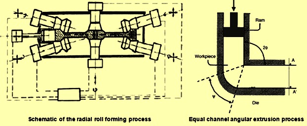
Fig 1 Radial roll forming and ECAE process
ECAE is another metal processing technique (Fig 1) developed by Segal in the former Soviet Union in the 1970s. In ECAE, metal flow comprises deformation through two intersecting channels of equal cross-sectional area. The imparted strain is a function primarily of the angle between the two channels, 2 phi, and the angle of the curved outer corner, psi. For 2phi = 90 and psi =0, for example, the effective strain is approximately equal to 1.15. By passing the work piece through the tooling many times, very large deformations can thus be imposed. This process has been studied as a means to refine microstructure and to control crystallographic texture. In many cases sub microcrystalline grain structures are developed.
A large amount of work has been performed on Al, Al alloys, Cu, iron, Ni, and Ti. Though the maximum attention has been focused on square or round billet products, ECAE has also been used to produce ultrafine grain plate materials for use as is or as preforms for subsequent sheet rolling. Also, effort has been made to modify the ECAE concept to allow continuous, rather than batch, processing. Such efforts have been limited to thin cross-section products such as wire, rod, and sheet.
Incremental forging is a closed die forging process in which only a portion of the work piece is shaped during each of a series of press strokes. The process is similar to open die forging (cogging) of ingots, billets, thick plates, and shafts. In contrast to such operations, however, impression dies (not flat or V-shaped tooling) are utilized. The primary applications of the technique are very large plan-area components of high temperature alloys for which die pressures can easily equal or exceed 140 to 280 N/Sq mm. In such instances, part plan area is limited to around several thousands of square centimeters for the very large presses (50,000 tons). By forging only a portion of the part at a time, however, reduces the press requirements.
Applications of the technique include large, axisymmetric components for land based gas turbines made from Ni based alloy and various Ti-Al based structural components for airplanes. The latter parts had plan areas of the order of 30,000 square centimeters. Here, part symmetry and forging design play a critical role in the design of incremental forging processes. Forging design, representing a key feature of incremental forging, is frequently highly specialized and proprietary in nature.
Micro forming is a technological process generally defined as the production of parts or structures with at least two dimensions in the sub millimeter range. Most of the developments in this area have been driven by the needs of the electronics industry for mass produced miniature parts. Major challenges in micro forming fall into one of the four broad categories namely (i) material of the work piece, (ii) tooling, (iii) equipment, and (iv) process control. As an example, the flow and failure behaviour of a work piece with only one or several grains across the section subjected to large strains can be very different from that of its poly crystalline counterpart used in macro bulk forming processes. Micro forming operations include cold heading and extrusion of wire. For example, the bulk forming of Cu pins via forward rod extrusion and backward (can) extrusion to produce a shaft diameter of 0.8 mm and a wall thickness of 125 micrometers. For this and similar micro operations, challenges include handling of small preforms, manufacture of tooling with complex inner geometry, tooling alignment, and the overall precision of the forming equipment.
Materials related developments
The materials related developments which have taken place include break-through in the bulk forming of new materials, increased control of microstructure improvement using a specialized TMP, and the development of advanced tools for predicting microstructure and texture evolution.
New materials for which substantial progress has been made since 1990s include structural intermetallic alloys and discontinuously reinforced metal-matrix composites (MMCs). For intermetallic alloys, bulk forming approaches have been most dramatic for aluminide based materials. Bulk forming on a commercial scale has been used for MMCs with Al alloy and, to a lesser extent, Ti alloy matrices.
Iron-aluminide alloys based on the Fe3Al compound are probably the structural intermetallic materials that have been produced in the largest quantities to date. These materials show outstanding oxidation and sulphidation resistance and potentially lower the cost as compared to the stainless steels with which they compete. Hence, there are a number of potential applications for these iron aluminides which have been identified. These include metalworking dies, heat shields, furnace fixtures and heating elements, and a variety of automotive components.
In recent years a large amount of work has been carried out with regards to the development of techniques for the hot extrusion, forging, and rolling of ingot-metallurgy (I/M) Fe3Al-base alloys at temperatures in the range of 900 deg C to 1200 deg C. The wrought product is then warm rolled to plate or sheet at temperatures between 500 deg C and 600 deg C to produce material with room temperature tensile ductility of 15 % to 20 %. However wrought Fe3Al alloys do not have adequate workability for cold rolling or cold drawing. Ti aluminide alloys based on the face centered tetragonal (fct) gamma phase (TiAl) represent another type of aluminide material for which significant progress has been made toward commercialization. The gamma Ti aluminide alloys have a number of applications as lightweight replacements for super alloys in the hot section of airplane engines and as thermal protection systems in hypersonic vehicles.
Substantial efforts have also been made with regards to the development of a variety of metalworking techniques for both the I/M and powder-metallurgy (P/M) materials. These materials were once thought to be unworkable. For example, isothermal forging and canned hot extrusion techniques have been established for the breakdown of medium scale to large scale ingots. New can designs and the use of a controlled residence time between billet removal from the preheat furnace and deformation have considerably enhanced the feasibility of hot extrusion. In particular, the residence time is chosen in order to develop a temperature difference between the sacrificial can material and the Ti aluminide preform; by this means the flow stresses of the two components is similar, thereby promoting uniform co-extrusion.
Secondary processing of parts is being more frequently conducted through isothermal closed die forging. Careful can design and understanding of temperature transients also have enabled the hot pack rolling of gamma Ti aluminide sheet and foil products used in subsequent superplastic forming operations. A key to the success of each of these processes has been the development of a detailed understanding of the relevant phase equilibria / phase transformations and the effects of microstructure, strain rate, and temperature on failure modes during processing.
Discontinuously reinforced Al MMCs (DRA MMCs) have been synthesized and subsequently bulk formed by a variety of methods. The majority of MMCs have been based on Al matrices with silicon carbide (SiC) particulate or whisker reinforcements synthesized in tonnage quantities by I/M or P/M approaches. In the I/M method, which is most often used for automotive parts, the ceramic particles are introduced and suspended in the liquid Al alloy prior to casting using a high energy mixing process. In the P/M approach, most often used for aerospace materials, the matrix and ceramic powders are blended in a high shear mixer prior to canning and outgassing. Following the casting/canning operations, conventional rolling, extrusion, and forging processes are used to make billet and plate products. Secondary processing may include rolling (to make sheet), extrusion (such as automotive drive shafts, fan exit guide vanes in commercial jet engines, and bicycle frame tubing etc.), and closed die forging (such as helicopter rotor blade sleeves, automobile engine pistons, and connecting rods etc.). Cast and extruded DRAMMC drive shafts with Al matrix and alumina reinforcements have also been introduced for pickup trucks and sports cars. Similarly, extrusion and upsetting of pressed and sintered Ti-6Al-4V reinforced with TiB2 particulate have been used to mass produce automobile and motorcycle engine valves.
Processing by TMP refers to the design and control of metalworking and heat treatment stages in an overall production process in order to enhance final microstructure and properties. Initially TMP was developed as a method for producing high strength or high toughness micro alloyed steels via (ferrite) grain refinement and controlled precipitation. Present trends in the TMPs for ferrous alloys are focusing on the development of carbide free steels with bainitic micro-structures to obtain even higher strength levels.
TMP is now also being used routinely for Ni base and Ti base alloys. Two examples of recent developments in the TMP for the Ni-base super alloys, intended to improve damage tolerance or creep resistance in service, involve techniques to produce a uniform intermediate grain size or a graded microstructure. The former technique is especially useful for the manufacture of P/M super alloys. In this example, TMP consists of isothermal forging of consolidated-powder preforms followed by super-solvus heat treatment. To achieve the desired final grain size after super-solvus heat treatment, however, forging need to be performed in a very tightly controlled strain, strain-rate, and temperature window for each specific material. Lack of control during deformation can result in uncontrolled grain growth during the succeeding super-solvus heat treatment, leading to isolated grains or groups of grains which are several orders of magnitude bigger than the average grain size. Processes to develop graded microstructures in super alloys consist of local heating above the solvus temperature to dissolve the grain boundary pinning phase (example is gamma prime) and thus facilitate grain growth in these regions while other portions of the component are cooled.
TMPs for Ti alloys include processing to produce ultrafine grain billet, ‘through transus’ forging, and final heat treatment to obtain graded microstructures. Methods to obtain ultrafine billet microstructures in alpha/beta Ti alloys depend on special forging practices for partially converted ingots containing an initial transformed beta (colony / basket weave alpha) microstructure. In one method, multistep hot forging along three orthogonal directions is conducted at strain rates of the order of 10?³s?¹ and a series of temperatures in the alpha/beta phase field. By this means, an alpha grain size of 4 to 8 mm with good ultrasonic inspectability is obtained. In a similar method, warm working, involving very high strains and somewhat lower temperatures (around 550 deg C to 700 deg C), has been found to yield a sub microcrystalline alpha grain size.
Through transus forging of alloys is a TMP which combines aspects of beta and alpha-beta forging in order to develop a microstructure with both high strength and good fracture toughness/fatigue resistance. By working through the transus, the development of a continuous (and deleterious) layer of alpha along the beta grain boundaries is avoided. Instead, a transformed beta matrix microstructure with equiaxed alpha particles on the beta grain boundaries is produced. However, if forging is conducted to temperatures that are too low, undesirable equiaxed, primary alpha is nucleated within the matrix. To help meet the tight limits on temperature for the process, therefore, hot die forging coupled with finite element modeling for process design are being used.
As with Ni base super alloys, special heat treatments have been developed to provide dual (and graded) microstructures in alpha-beta Ti alloys. Most of these methods comprise local heating of selected regions of a part above the beta-transus temperature followed by controlled cooling. Information on beta annealing under continuous heating conditions and the effect of texture evolution on beta grain growth is vital for the selection of heating rates and peak temperatures for such TMP routes. In addition, since the decomposition of the metastable beta is very sensitive to cooling rate, dual microstructure TMPs are being used to produce components with a gradation of microstructure morphologies.
Models for the microstructure evolution
Models for the microstructure evolution usually fall into two broad categories namely (i) phenomenological, and (ii) mechanism based. Phenomenological models for the microstructure evolution have been developed to correlate measured microstructural features and imposed processing conditions and are therefore typically valid only within the specific range of the observations. As an example, the evolution of recrystallized volume fraction and recrystallized grain size which evolve during hot deformation (due to ‘dynamic’ recrystallization) can be described as a function of the imposed strain, strain rate, and temperature.
Similar models deals with the evolution of grain structure during annealing following cold or hot working as a function of time due to ‘static’ recrystallization. In both the cases, the recrystallized volume fraction usually follows a sigmoidal dependence on strain or time. Phenomenological models of dynamic and static recrystallization have been developed for a variety of steels, Al alloys, and Ni base alloys. Grain growth during heat treatment of single phase alloys without or with a dispersion of second phase particles can also be quantified using phenomenological equations such as that based on a parabolic fit of observations for a very wide range of metals and alloys.
Mechanism based models have also been examined since 1990s for the modeling of the microstructure evolution during hot working and annealing. These models incorporate deterministic and statistical aspects to varying degrees and seek to quantify the specific mechanism underlying microstructure changes. Most of the models incorporate physics based rules for events such as nucleation and growth during both recrystallization and grain growth. The effects of stored work, concurrent hot working, crystallographic texture, grain boundary energy and mobility, second phase particles, and so forth on microstructure evolution are normally been described by these models. Accurate models of this type can delineate microstructure evolution over a broader range of processing conditions than phenomenological models and are also very useful for processes involving strain rate and temperature transients. In addition, the models can provide insight into the source of observed deviations from classical Avrami behaviour during recrystallization or non-parabolic grain growth. Two principal types of mechanism based models are those based on cellular automaton (primarily used for recrystallization issues) and the Monte-Carlo/Potts formalism (used for both recrystallization and grain-growth issues). Both of these formulations seek to describe phenomena at the meso (grain) scale. Challenges with regard to the validation and industrial application of many mechanism-based models still remain, however, largely because of the shortage of reliable material property data.
Texture evolution models are basically of two main categories namely (i) those principally for the prediction of deformation textures or (ii) those predicting recrystallization/transformation textures. Powerful computers availability these days have speeded the development of such modeling techniques. Models for the depiction of deformation texture is more advanced compared to the models for predicting recrystallization / transformation textures. Deformation texture modeling is based on the slip and twinning processes and the associated crystal rotations to predict anisotropic plastic flow and texture evolution. Models of this kind include lower bound and upper bound methods in which either stress or strain compatibility is enforced among the grains in a polycrystalline aggregate, respectively. Upper bound models in many cases provide reasonable estimates of deformation texture evolution. However, more detailed methods, which incorporate strain variations from grain to grain (self-consistent models) as well as within each grain (crystal-plasticity FEM techniques, or in short CPFEM), give the promise of even more accurate predictions. The CPFEM method is also useful for the determination of local conditions that give rise to cavitation, spheroidization, and so forth as long as that the physics associated with such processes can be measured in terms of the field variables used in these programmes.
A comparatively recent development in texture modeling is that associated with the recrystallization or transformation phenomena during or following hot deformation. As an example, the textures which evolve during hot working are a result of both dislocation glide and dynamic recrystallization. Texture evolution can be measured by mechanisms such as oriented nucleation and selective growth. In the case of oriented nucleation mechanism, recrystallization nuclei are formed in those grains that have undergone the least shear strain (dislocation glide). Selective (faster) growth is then expected to occur for nuclei of particular mis-orientations with respect to the matrix.
Process simulation and design
Due to the availability of powerful and cheap computer hardware and software these days, a veritable revolution has taken place in the design of the bulk forming processes using advanced modeling and optimization methods since 1990s. Advances in process simulation have been accelerated mainly by the development of general purpose FEM programmes. The speed, accuracy, and user friendliness of FEM programmes has been aided by optimization of the element type used in the programme such as the development of automatic meshing and re-meshing practices, the introduction of advanced solving techniques, and the incorporation of advanced graphics user interfaces (GUIs).
In the 1980s, early FEM programmes were used to predict metal flow in simple two dimensional problems which are in non-steady-state (such as closed die forging). Since the early 1990s, two dimensional uses have grown considerably. In addition, increasingly powerful FEM programmes have been used to simulate a number of three dimensional (3-D) forging issues. Presently FEM uses include the design of tooling for forgings which need (i) multiple die impressions, (ii) the simulation of open-die forging processes, and (iii) various steady-state issues (examples are extrusion, drawing of flat and shape, pack rolling, and ring rolling). The simulation of open die forging processes for billet products (cogging, radial forging) is mainly challenging because of the size of the work piece, the higher number of forging blows, and the rotation of the work piece between blows, among other factors. Other complex 3-D problems, which have been studied using FEM, include orbital forging, forging of crankshafts, extrusion of shapes, and helical-gear extrusion.
In addition to predictions of metal flow and die fill (and associated metal flow defects such as laps, folds, and pipe), FEM is also being used regularly to analyze the evolution of microstructure and defects within the work piece, die stresses/tooling failure, and so on. For example the prediction of defects due to cavitation and ductile fracture normally relies on continuum criteria (example is the Cockcroft and Latham maximum tensile work criterion) and FEM model predictions of stresses and strains. Likewise, in the area of microstructure evolution, variations of fraction recrystallized and recrystallized grain size developed within a work piece during hot working are typically assessed using phenomenological models and FEM predictions of imposed strain, strain rate, and temperature. Such methods have been relatively successful for non-steady-state processes such as closed-die press and hammer forging as well as for forging of steels and super alloys.
FEM based models are also been used for the prediction of microstructure evolution during steady state processes (hot rolling of steel). As with many multistage steel rolling processes, microstructure changes are controlled mainly by static recrystallization and grain growth between rolling stands. The fraction recrystallized and retained work is used to estimate the flow stress of the material as it enters each successive roll stand. Also some models uses the temperature history after rolling and cooling transformation curves to model the decomposition of austenite during cool down.
Recently, an FEM modeling procedure was developed within the framework of the commercial programme to predict residual stresses which develop during heat treatment and distortion during subsequent machining processes for ferrous and Ni base super alloy parts. The FEM model for heat treatment assumes that the residual stresses developed during the forging and cool down operations are relieved early during solution heat treatment. Thus, residual stresses are induced mainly during quenching and continue to evolve during the rest of the heat treatment process. The rapid cooling during quenching produces severe temperature gradients within the part and gives rise to non-uniform strains. The development of residual stresses is thus handled using a standard elasto-plastic constitutive formulation in the FEM programme. The effect of phase transformations during cooling (as in steels) on residual stresses is also treated in the recent FEM heat treatment programmes. For this purpose, phase-transformation data are incorporated in order to quantify the volume changes accompanying specific transformation products which are formed in different areas of a part. To model subsequent stress-relief operations, creep models are incorporated into the programme.
Process design and optimization methods represent the most important methodology in the development of computer-aided applications for bulk forming processes. The introduction of innovative process simulation tools has replaced former methods involving costly and time consuming method of machining and tryout of dies. Nevertheless, the selection of preform designs and processing conditions for the determination of optimal die fill, microstructure evolution, die life and so on still can involve considerable trial and error and thus multiple simulations are needed when computer-modeling techniques alone are used. Hence, integrated systems have been now developed to automate the optimization process. For bulk forming processes, such systems include an FEM metal-forming programme, a solid-geometry module, and an optimization programme. Although the specifics of each issue vary, the overall approach typically comprises three elements namely (i) choice of an objective function and constraints, (ii) calculation of the objective function (as is being done by the FEM simulation programme), and (iii) a search for the combination of design parameters that provide a minimum or maximum for the objective function. In bulk forming, objective functions usually include forging weight (usually minimum), die fill (usually minimum under fill), uniformity of strain or strain rate (usually maximum uniformity) etc. Constraints can include maximum or minimum allowable strain, strain rate, or temperature to prevent metallurgical defects, the specification of maximum die stresses or press loading etc.
Leave a Comment