Gaskets and Their Types
Gaskets and Their Types
The cost of leaky joints in a steel plant can be staggering. Gaskets perform an important role in the prevention of fluid leakage from pipes and equipment parts in the steel plant.
A gasket is a compressible material, or a combination of materials, which when clamped between two stationary members prevents the passage of the media across those members. The gasket material selected must be capable of sealing mating surfaces, resistant to the medium being sealed, and able to withstand the application temperatures and pressures.
Generally, gaskets are called upon to affect a seal across the faces of contact with the flanges. Permeation of the media through the body of the gasket is also a possibility depending on material, confined media, and acceptable leakage rate.
A gasket is normally placed in between two objects in order to prevent leakage of any kind of the pressurized or not pressurized media. Most important is the compression set of a gasket to adapt to flange irregularities and to any dimensional changes of the flange system caused by temperature changes during operation.
Gaskets are used to create a static seal between two stationary members of a mechanical assembly and to maintain that seal under operating conditions which may vary dependent upon changes in pressures and temperatures. If it is possible to have perfectly mated flanges and if it is possible to maintain an intimate contact of these perfectly mated flanges throughout the extremes of operating conditions, then the gaskets are not required. However this is virtually impossible because of the following.
- Size of the flanges and/or the vessel
- Difficulty in maintaining extremely smooth flange finishes during handling and assembly
- Corrosion and erosion of the flange surfaces during operations
- Large number of flanged joints needed in a steel plant, and hence its commercial implications.
Because of above, relatively inexpensive gaskets are used to provide the sealing element in these mechanical assemblies. In most cases, the gasket provides a seal by external forces flowing in the gasket material into the imperfections between the mating surfaces. It follows then that in a properly designed gasket closure, the following three major considerations are to be taken into account for achieving a satisfactory seal.
- Availability of sufficient force for the initial seating of the gasket. In other words, adequate means are to be provided for the flow of the gasket into the imperfections in the gasket seating surfaces.
- Availability of sufficient forces for maintaining a residual stress on the gasket under operating conditions to ensure that the gasket remains in intimate contact with the gasket seating surfaces to prevent leakage.
- Selection of the gasket material is to be such that it withstands the pressures exerted against the gasket, satisfactorily resists the entire temperature range to which the closure is exposed and withstands corrosive attack of the confined medium.
Hence the requirements for a gasket are (i) good compressibility and face adaptability, (ii) good recovery, (iii) strength, (iv) limited relaxation, (v) chemical resistance, and (vi) temperature resistance.
Types of gaskets
Gaskets are normally categorized into the following three types (Fig 1).
- Non-metallic – Sheet materials are used in low to medium pressure services. With careful selection these gaskets are not only suitable for general service but also for extreme chemical services and temperatures. Examples are elastomers, cork, compressed fibre sheets, poly tetra fluoro ethylene (PTFE), Bi-axially orientated reinforced PTFE, graphite, thermiculite, and insulating gaskets etc.
- Semi-metallic – These are composite gaskets consisting of both metallic and non-metallic materials. The metal provides the strength and the resilience of the gasket and the non-metallic component provides the conformable sealing material. These gaskets are suitable for low and high pressure and temperature applications. A wide range of materials is available. Examples are spiral wound gaskets, gaskets with covered serrated metal core, metal jacketed gaskets, and metal reinforced gaskets etc.
- Metallic – These gaskets can be fabricated in a variety of shapes and sizes recommended for use in high pressure/temperature applications. These gaskets require a much higher quality of the sealing surface than non-metallic gaskets. Except for weld ring gaskets, high loads are required to seat metallic gaskets, as they rely on the deformation or coining of the material into the flange surfaces. Examples are ring type joints, lens rings, weld rings, and solid metal gaskets etc
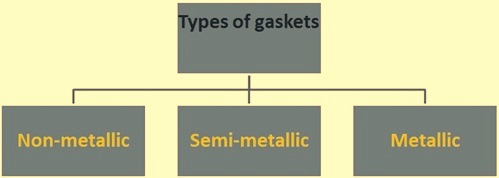
Fig 1 Types of gaskets
Each of these types has its own advantages. The optimum gasket material needs to have the following characteristics. It needs to have the chemical resistance of PTFE, the heat resistance of graphite, the strength of steel, it requires a zero seating stress such as soft rubber, and be inexpensive. Obviously there is no known gasket material that has all these characteristics and each material has certain limitations that restrict its use. It is possible to overcome limitations partially by several methods such as including the use of reinforcing inserts, combining it with other materials, varying the construction or density, or by designing the joint itself to overcome some of the limitations. Obviously, mechanical factors are important in the design of the joint.
Many factors are to be considered when selecting a gasket to ensure its suitability for the intended application. Gasket properties as well as flange configuration and application details are part of the selection process. The physical properties and performance of a gasket varies extensively, depending on the type of gasket selected and the materials from which it is manufactured. Physical properties are important factors when considering gasket design and the primary selection of a gasket type is based on the following.
- Temperature of the media to be contained
- Pressure of the media to be contained
- Corrosive nature of the application
- Criticality of the application
Gasket connection and making of a seal
The flange connection is the widest spread gasket application. The flange connection is a sealing system, which consists of (i) flanges, (ii) gasket, and (iii) bolts. Only the right choice and combination of these three individual parts results in a leakage free operation with long service life.
Gasket is a device for sealing two surfaces, by storing energy between them. The gasket reacts to the forces generated by the bolts, and therefore the work and energy imparted to the bolted joint becomes ‘stored’ within the gasket itself.
On seating, the gasket needs to be capable of overcoming the macro and micro imperfections. Macro defects are imperfections such as flange distortions, non-parallelism, scoring, troughs, while superficial imperfections such as minor scratches and minor scores are considered micro imperfections.
In order to ensure the maintenance of the seal throughout the life expectancy of the assembly, sufficient stress must remain on the gasket surface to prevent leakage. The residual bolt load on the gasket at all times must be greater than the hydrostatic end force acting against it. The hydrostatic end force is the force produced by the internal pressure which acts to separate the flanges.
A seal is made by the action of force upon the gasket surface. This force, which compresses the gasket, causes it to flow into the flange macro and micro imperfections. The combination of contact stress, generated by the applied force between the gasket and the flange, and the densification of the gasket material, prevents the escape of the confined fluid from the assembly.
Basically there are the following four different methods which are used either singly or in combination to achieve this unbroken barrier.
- Compression – This is by far the most common method of making a seal on a flange joint and the compression force is normally applied by bolting.
- Attrition – This is a combination of a dragging action combined with compression such as in a spark plug gasket where the spark plug is turned down on a gasket that is both compressed and screwed into the flange.
- By heat – Example is the case of sealing a bell and spigot joint on cast iron pipe by means of molten lead. However, in such case after the molten lead is poured, it is tamped into place using a tamping tool and a hammer.
- Gasket lip expansion – This is a phenomenon which occurs due to edge swelling when the gasket is affected by confined fluid. This causes the gasket material to swell and increase the interaction of the gasket against the flange faces.
Forces acting on a gasketed joint
Forces acting on a gasket joint are the following
- Internal pressure – These are the forces continually trying to unseal a gasketed joint by exerting pressure against the gasket (blowout pressure) and against the flanges holding the gasket in place (hydrostatic end force).
- Flange load – it is the total force compressing the gasket to create a seal. It is the effective pressure resulting from the bolt loading.
- Temperature – Temperature creates thermo-mechanical effects, expanding or contracting the metals, affecting the gasket material by promoting ‘creep relaxation’ which is a permanent strain or relaxation quality of many soft materials under stress. The effect of certain confined fluids may become increasingly degrading as temperature rises and attack upon organic gasket materials is substantially greater than at the ambient temperatures (about 25 deg C). As a rule, the higher the temperature, the more critical becomes the selection of the proper gasket. .
- Medium – It is the fluid (liquid or gas) against which the gasket is to seal.
- General conditions – These include type of flange, flange surfaces, type of bolt material, spacing, and tightness of the bolts etc.
There are other shock forces that may be created due to sudden changes in temperature and pressure. Creep relaxation is another factor that may come into the picture. The initial compression force applied to a joint must serve several purposes. This includes the following.
- It must be sufficient to initially seat the gasket and flow the gasket into the imperfections on the gasket seating surfaces regardless of operating conditions.
- Initial compression force must be great enough to compensate for the total hydrostatic end force that would be present during operating conditions.
- It must be sufficient to maintain a residual load on the gasket/flange interface.
From a practical standpoint, residual gasket load must be a few times of the internal pressure if a tight joint is to be maintained. This unknown quantity varies depending upon the type of gasket being used. Actually it is the ratio of residual unit stress (bolt load minus hydrostatic end force) on gasket to internal pressure of the system. The larger the value, the more conservative the flange design would be, and the more assurance the designer has of obtaining a tight joint.
Each of the above factors requires consideration before an effective gasket material is finally chosen. However, the proper gasket may often be rejected because failure occurred due to a poorly cleaned flange face, or improper bolting-up practice. These details require careful attention, but if complied with, do help eliminate gasket blowout or failure.
Gasket seating
There are two major factors to be considered with regard to gasket seating.
The first is the gasket material itself. There are minimum designs seating stresses for a variety of gasket materials. These designs seating stresses range from zero kg/sq cm for so called self-sealing gasket types such as O-rings to more than 1800 kg/sq cm to properly seat solid flat metal gaskets. Between these two extremes there are a multitude of materials available to the designer enabling him to make a selection based upon the specific operating conditions under investigation.
The second major factor to take into consideration is the surface finish of the gasket seating surface. As a general rule, it is necessary to have a relatively rough gasket seating surface for elastomeric and PTFE gaskets on the order of magnitude of 20 micro millimeters. Solid metal gaskets normally require a surface finish not rougher than 2.5 micro millimeters. Semi-metallic gaskets such as spiral wound fall between these two general types. The reason for the difference is that with non-metallic gaskets such as rubber, there must be sufficient roughness on the gasket seating surfaces to bite into the gasket thereby preventing excessive extrusion and increasing resistance to gasket blowout. In the case of solid metal gaskets, extremely high unit loads are required to flow the gasket into imperfections on the gasket seating surfaces. This requires that the gasket seating surfaces be as smooth as possible to ensure an effective seal. Spiral-wound gaskets, which have become extremely popular in the last fifteen to twenty years, do require some surface roughness to prevent excessive radial slippage of the gasket under compression. The characteristics of the type of gasket being used dictate the proper flange surface finish that must be taken into consideration by the flange designer and there is no such thing as a single optimum gasket surface finish for all types of gaskets. The problem of the proper finish for gasket seating surface is further complicated by the type of the flange design. For example a totally enclosed facing such as tongue and groove will permit the use of a much smoother gasket seating surface than can be tolerated with a raised face.
Gasket behaviour
There the following four parameters which determines the gasket behaviour.
- Stress relaxation – The stress relaxation performance or the stress retention property of a gasket is vital in maintaining the level of energy stored in the joint, which affects the seal. Relaxation can occur at the flange-gasket interface as well as within the gasket material itself. This characteristic is particularly relevant in relation to non-metallic sheet jointing materials, where there are recognized test procedures available for examining relaxation effects. These involve stressing the gasket to a pre-determined amount and subjecting it to elevated temperatures for a given time. At the end of the test the remaining stress level is measured, where materials giving the higher readings are generally considered to be more successful. Materials with high rubber/elastomer content are expected to relax significantly as the rubber/elastomer decays at temperature. In case of fibre sheet jointing materials, thick materials exhibit increased relaxation over thin ones. Thus, the thinnest gasket possible is always be used, and needs only be sufficiently thick to take up any flange distortion and misalignment.
- Tensile strength – Tensile strength is not necessarily the most important function of a gasket material. Expanded graphite for example is relatively weak, though it performs very well as a gasket material, with a high degree of sealability in a wide range of media. If a gasket is adequately loaded on a flange with the correct surface finish, then the clamping forces resist the tendency for the joint to ‘blow-out’ at pressure. However, if the joint is relatively thick (i.e. with a significant area exposed to the system pressure) and inadequately compressed, then the internal pressure forces on the inside edges have to be resisted by the tensile strength of the gasket. Again, the thinner the gasket the less relaxation occurs internally as well as exposing less area to the system pressure that is trying to force the gasket from between the flanges.
- Effect of flange surface finish – Normally, standard piping flanges are supplied with a light gramophone-finish groove across the gasket seating face. This finish is suitable for non-metallic and semi-metallic gaskets, whereas values for metallic gaskets are specified within relevant standards for ring joint gaskets. This finish tends to ‘grip’ the gasket material and thereby limits the creep across the flange faces. The surface finish must not be so rough as to allow a leak path under the gasket, where the gasket is unable to deform effectively to fill the gramophone groove. The use of pastes on the gasket surface actually worsens sealing performance as these can fill-in the surface finish allowing stress relaxation to occur. Any flange damage is to be rectified before a joint is re-made. The spirally grooved (gramophone) surface finishes as specified in common flange standards generally provide a good surface for most gasket types. Wherever possible, the mating flanges should be of the same material and machined identically. It is also important that the flange surfaces are flat, free of imperfections, and as far as practicable are parallel.
- Load sealability – It is a fact that all gaskets leak to varying degrees. For example, whilst an assembly may be built and hydro-tested successfully, if it is pressurized with helium for example and the flange encapsulated, it may be possible to detect a small mass-leak rate of the helium, after a period of time, using a mass-spectrometer. This leak-rate might otherwise be considered undetectable in general industrial terms, though the load sealability tests that are conducted by gasket manufacturers and research institutes are invaluable when looking at critical sealing applications. Further it may be assumed that in the free, uncompressed state, that a non-metallic gasket may have some internal porosity, as when manufactured, the material may not be perfectly homogenous. Thus, any micro-porosity holes in the structure allow leakage until the applied seating stress causes them to close. As the gasket densifies under load, such porosity becomes increasingly less and the joint continues to tighten becoming progressively denser. Therefore, a load leakage test on a gasket tends to produce an exponential-decay curve format thus: A curve of the load-compression characteristics will be very similar, again showing how the material densifies under increasing stress as any micro-porosity is closed within the material structure. The gasket becomes increasingly hard to compress with increasing applied stress. Most gasket sealing tests are done on a loading- unloading cycle to see the effects of leakage as the gasket stress is reduced (by the hydrostatic force for example), after being loaded to a higher value. Thus, the sealing properties are quite complex, depending upon the initial and operational stress levels that are likely to occur in service. The flange rotation effects further complicates the theoretical stress levels upon the gasket element. For a given operating stress on a gasket, the leak-rate increases with increasing system pressure. Similarly, for a sheet gasket material, the leak-rate increases with material thickness, roughly in a proportional manner, (i.e. double the gasket thickness produces double the leak rate).
Leave a Comment