Blast Furnace Tap Hole and Tapping of the Furnace
Blast Furnace Tap Hole and Tapping of the Furnace
The operation of a blast furnace is a continuous process. The blast furnace continues to produce liquid iron (hot metal) and slag as long as it is in operation. The hot metal and slag accumulate in the hearth of the furnace, but since there is a limit to the amount that can be accumulated before it interferes with the furnace operation, hot metal and slag must be removed from the furnace at regular intervals. The tap hole also known as iron notch, is used for tapping the hot metal from the furnace. It is located slightly above the floor of the hearth.
Regardless of the specific tap hole configuration or operating philosophy, due to the addition of dynamic (often periodic) and more intense process conditions (exposure to higher temperatures leading to accelerated corrosion, greater turbulence, and elevated rates of mass and heat transfer), and higher concurrent thermo-mechanical forces (from thermal or flow shear stresses), the performance and longevity of the blast furnace is intimately linked to the performance of the tap hole. Hence tap hole is very critical to the blast furnace. It is the heart and the lifeline of the blast furnace since without a tap hole a blast furnace cannot exist. The criticality and relevance of tap hole continues even in the modern automated blast furnaces.
Tap hole is an essential part of a blast furnace. Large furnaces usually have 2 to 4 tap holes and the drainage of hot metal and slag is practically continuous by periodically drilling and plugging the tap holes with one of the tap holes is always open and two alternate tapings usually overlap for some period of time. Medium or small sized blast furnaces have normally one tap hole and the time interval between two tappings generally varies from 30 min to 90 min. Some blast furnaces are equipped with a slag (cinder) notch (generally referred to as the monkey) for removing slag from the blast furnace, and it is located in a plane typically 1 m to2 m above the tap hole.
In earlier days when the burden of the blast furnace was not improved to present standards, the weight of the slag produced in the blast furnace was more than half the weight of the hot metal. The lower density of the slag caused it to fill up the space in the hearth above the metal, and it would interfere with the penetration of the blast air and the combustion process at the tuyeres long before the accumulation of hot metal had reached the desired amount for tapping. Hence it was necessary to remove the excess slag through the slag notch once or twice between two tappings. However presently because of better prepared burdens, the slag volumes are at around 250–320 kg/ton level. Therefore the monkey is seldom used and the slag is typically removed only through the tap hole during the blast furnace tapping.
Tapping, also referred to as casting or drainage, is a process that removes hot metal and slag from the furnace hearth. The tapping process critically determines the in-furnace gas pressure and residual amounts of iron and slag in the hearth. Poor hearth drainage usually leads to unstable furnace operation which is generally connected to marked losses in furnace productivity and campaign life. An inefficient tapping also gives rise to excessive accumulation of liquids and thus high liquid levels in the hearth. If the liquid slag approaches the tuyeres level, the reducing gas flow in the bosh is severely disturbed, often resulting in irregular burden descent.
A tapping cycle begins as the tap hole is drilled open and is terminated by plugging the tap hole with the tap hole mass when the furnace gas bursts out. At the end of the tapping, the gas-slag interface tilts down towards the tap hole and a considerable amount of slag remains above the tap hole level. The iron phase can be drained from levels below the tap hole because of the large pressure gradient that develops near the tap hole in the viscous slag phase. The average slag-iron interface is therefore lower than the tap hole level. Depending on a number of factors, such as liquid production rates, hearth volume and tapping strategies, the initial stage of a tapping cycle varies and can be categorized as follows.
- Iron first -This occurs if the slag-iron interface is above the tap hole level when the tap hole is drilled open. The tapping cycle starts with an outflow of iron only, and slag starts flowing later when the slag-iron interface has descended to the tap hole. After this, iron and slag are drained simultaneously until the end of the tapping. The time elapsed from the start of the tapping until slag enters the runner is called the slag delay.
- Simultaneous – This pattern appears if the slag-iron interface lies in, or at a finite depth below the tap hole when the tapping commences. The high pressure gradient in the slag phase can promote iron flow, or even drags iron up from below the tap hole. As a result, iron and slag are drained together during the whole period of tapping.
- Slag first- This is opposite to the iron first pattern. In this pattern slag flows out initially and iron after a delay. This is because the slag-iron interface is far below the tap hole as the tapping begins, and the phenomena can be observed in larger furnaces with multiple tap holes. The pressure gradient caused by the viscous slag is initially inadequate to lift iron up.
A primary requirement of tapping is to secure reliably the desired rate of furnace products. Thus, establishing the factors influencing tapping rate are important. Normally in large blast furnaces tapping rates of 7 ton/min, and liquid tapping velocities of 5 m/sec, in tap holes of 70 mm diameter and 3.5 m long, are typically encountered. Tap hole condition and tap hole length strongly influence the tapping rate. When the blast furnace is in operation, the tap hole is completely filled with a refractory material known as the tap hole mass.
Tap hole is normally exposed to an extremely dynamic environment with high temperature and pressure, frequent drilling and plugging, substantial chemical attack, and flow induced shear. During tapping, the tap hole is gradually eroded as the molten liquids flow through it. The greater the wear of the tap hole, the greater is the change in the liquid flow rates and the greater is the variation of liquid levels in the hearth. For the maintenance of a stable state at the tap hole thus facilitating the liquid removal from the hearth, an excess of high quality blast furnace tap hole mass is, in practice, injected in the tap hole when a tap is terminated. The tap hole mass accumulates and solidifies on the inside of the tap hole forming a protective layer with the shape of a ‘mushroom’, which is mainly concentrated directly below the tap hole and to a lesser extent sideways and above the tap hole. The tap hole therefore becomes longer than the depth of the corresponding hearth sidewall through which the tap hole is drilled. A longer tap hole can drain molten liquids from the inner part of the hearth and the circumferential flow can be suppressed. Also, longer tap holes can result in decreased drainage rates due to the frictional effect and thus lower the consumption of the tap hole mass. The size and shape of the mushroom layer has also have significant effect on the temperature variations of hearth lining during tapping.
When the time arrives for the furnace to be tapped, the tap hole need to be opened. It is essential that the tap hole is quickly and certainly be opened whenever required. Discounting the most primitive past practices of ‘pricking’ or ‘excavating’ for the opening of tap hole, a wide range of tap hole opening methods are adopted which include the following. (Fig 1)
- Manual oxygen lancing of the tap hole. This is normally to be minimized or during emergency only. It can lead to blister tap hole failure and can result into explosion.
- Drilling by drilling machine which can be electrically, pneumatically or hydraulically operated. The tap hole is drilled open using a drill rod of appropriate diameter and length in the drilling machine. The drill machine generally has both rotational and hammer capabilities. Normally, rotation only is required to open the tap hole, but if the tap hole mass is very hard just before the full length is reached, it might be necessary to utilize the hammer action. This, however, is avoided wherever possible as it damages the tap hole and the ‘mushroom’.
- Soaking bar technique – Soaking bar practice found favour in the furnace tapping as an emerging development to replace tap hole drilling in the 1980s. It involved pushing/hammering a 50 mm bar through the tap hole mass in the tapping channel. This promised to provide improved thermal conductivity from the inner hearth up the tapping channel to better bake and sinter tap hole mass. To open the tap hole, the bar was reverse hammered out of the tapping channel, now of well defined dimension, and with the promise of no risk of skew drilling or oxygen lancing damage. However, the practice had fallen out of favour by the 1990s, for reasons of requiring time consuming pre drilling to assist with soaking bar insertion, difficulty in accurately assessing the all critical drill depth and matching it to optimal tap hole mass addition, shorter tap hole mass curing times with increased risk of tap hole self opening, and other tap hole and ‘mushroom’ damage induced by hammering in bar installation and removal.
- Combination of drilling without opening, and deliberate lancing of the last remaining portion of the tap hole.
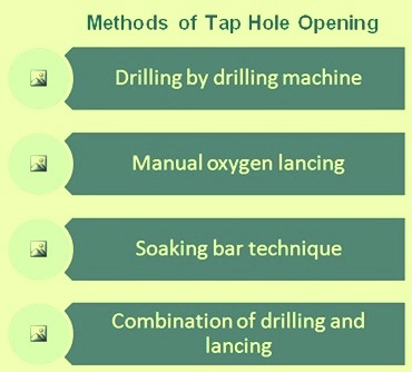
Fig 1 Tap hole opening methods
Tap hole wear mechanisms
Tap hole dimensions have a dominant influence on tapping rate. Hence , it is essential to consider factors which contribute to the wear of the tap hole. These factors are (i) penetration, (ii) corrosion, and (iii) erosion. The first step to refractory wear involves penetration of liquids in the refractory, the rate of which can be described by a capillary force driven flow. Once a liquid has penetrated the refractory, reaction with infiltrating liquid becomes possible through corrosion. Corrosion rate relates to how long a penetrated refractory has been at a temperature that supports the reaction. Further, when a refractory has been penetrated and further weakened by corrosion, erosion becomes possible if the shear stress induced by liquid flow is sufficient to remove refractory. Also the process conditions can influence liquid viscosity through temperature, while the rate of tapping affects the velocity gradient. At the tapping velocities of 1 m/sec to 5 m/sec the applied shear force is a few orders of magnitude lower than the hot modulus of rupture of most refractories. Hence tap hole refractory erosion cannot occur until the refractory structure has been first weakened by the liquid penetration and corrosion. Hence blast furnace operation depends critically on a ‘maintainable’ baked and sintered annulus of tap hole mass to line the tapping channel to protect the tap hole refractory. Consequently, far more attention is needed to be given to the issue of tap hole mass sintering and erosion properties.
Due to the potential damage to tap holes because of oxygen lancing, it is always better to drill open the tap hole. This typically results into sacrificing the drill bit and potentially the drill rod.
In many places, a combination of deep drilling followed by plug oxygen lancing is practiced deliberately. The aim is to drill through the tap hole mass as (consistently) deep as possible, until drill resistance is encountered owing to a ‘plug’ of metal/residual entrained slag. Attempting to drill further through this plug often leads to unintended skew drilling and often results in the drill simply getting stuck in the tapping channel. Even with reverse percussion hammering, it may become impossible to free a stuck drill bit and rod, requiring the cast house operator to resort to oxygen lancing to remove the obstruction.
In combination practice, the drill is then withdrawn, the drill length accurately (but manually) measured with a gradated drill-T, which simultaneously verifies that the drilling was not off-centre. Once the drill hole is positively confirmed as straight, oxygen lancing of the (short) remaining tapping channel plug is then performed to open the tap hole. This usually requires a minimum of lancing (less than one lance pipe).
Tap hole drilling requirements
The requirements to control and optimize the rate of drainage to the tap hole (to lower liquid velocities and wear of the furnace lining) and associated tapping rate through it (controlled liquid tap with stable post tap hole conditions), impose a need to maintain a constant and optimal tap hole length and smooth shape. This usually is as long as practicably achievable, while maintaining a near cylindrical channel shape of defined diameter. In reality, some extent of fluting towards the hot face with erosion at the hot face is present because of tapping channel temperatures, drill depths and their distributions. Further since there is a high ratio of slag volume to metal volume , it is often argued that the decision for diameter and tapping practice must be focused on slag. This highlights a role of reliable drilling, as it represents the primary means to control tap hole diameter.
Tap hole drilling equipment and control
Due to excessive risks of skew drilling, the accurate alignment of mud guns and drills are to be checked and, if necessary, recalibrated at the start of each shift. Tap hole centering notches are to locate the tap hole mass to help keep the drill from ‘walking off’ from the centre of the tap hole. In addition, guided and stiff drill rods are essential to reduce excessive drill flex and secure a straight centered tap hole. Guide systems include automatic travel to within limits, followed by a hydraulic pin being physically positioned down into latch hooks. For drilling long blast furnace tap holes (3.5 m to 4 m), additional hydraulic rod devices are fixed to the drills to prevent bending of the drill rods and drilling off the tap hole axis.
Drill rod and bits
Drill bit shape and material (carbide or heat resistant Cr-Ni alloy tips) are important. The ability to retain a sharp cutting edge to cut, rather than hammer, through the tap hole mass, is important with the bit cutting face presented to a debris and dust free face to drill. Drill bit diameter is usually controlled within a range of 33 mm to 65 mm. Where hammering is considered important, an inside bit face that is totally flat, to maximize transmission of impact energy coupled with transition from spherical to semi-spherical carbide shapes is used. Air scavenging is typically used to achieve a cleared hole, additionally providing some cooling of the drill bit to help prolong its life.
There are two opposing effects of drilling on control of tapping channel diameter. With premature bit wear there is a tapping channel negative fluting (diameter decreasing evenly down to the drill rod diameter towards the hot face. More frequently though, a bit that fails to retain its cutting edge tends to wander, results into a positive fluting (enlarging the hole to the hot-face), or a ‘mushrooming’ effect. Traditional rock drill bit designs provide some increased resistance to this, and are often preferred, despite still requiring drill bit replacement every tap. Also progression from threaded, to bayonet, drill rod couplings is reported to limit the incidence of drill rods jammed tightly in couplings.
The direct consequence of a smooth straight tapping channel is a consistent smooth tapping stream. On the contrary, a tapping channel with an inner corkscrew shape induces a rotating and spraying tapping stream. Softer drilling with ‘let the drill do the work’ and not try to force the tap hole open using maximum force that can bend the drill rod, and produce a corkscrew condition, results into smooth tapping stream.
Tap hole closure
It is essential that the tap hole is closed with a high degree of certainty and also to ensure that the desired volume of tap hole mass has been installed. It is to be additionally ensured that upon mud gun retraction unplanned tap hole self opening does not occur. Total elimination of self opening is very important.
Normally sophisticated and powerful mud guns are used for the closure of the tap hole. Again, the importance of considering mud gun, tap hole mass and tap hole operating practice holistically as a fully integrated system cannot be understated. Coupling of a hard new generation tap hole mass with an old weak mud gun incapable of properly delivering the tap hole mass into the tap hole, is bound to fail. Generally a well through ‘design’ of tap hole mass is usually a compromise between ‘equipment capability’ and ‘process’ requirements.
While manual plugging may seem at first glance seem extremely simplistic and requiring direct interface of the operator with a hot tapping stream, if incorrectly controlled, excessive tap hole clay addition capable through automated mud guns potentially can have a destructive (but often hidden), action on a tap hole and lining environs.
A perfectly cylindrical 1 m long tapping channel of 50 mm diameter requires theoretically only 2 litres of tap hole mass to fully fill it. This increases to 5 litres if worn on average to 80 mm diameter, by either positive fluting (exacerbated by any oxygen lancing and/or enlargement by bath wear of the tap hole hot face), or negative fluting down the tapping channel. It is quite staggering to compare this quantity of tap hole mass with the mass being used for blast furnaces of 1.8 m to 2 m, or more usually 2.5 m to 4 m tap hole length, of ‘as little’ as 10 litres to 20 litres, to 50 litres to 120 litres to even 200 litres to 300 litres of tap hole mass per closure, when trying to stabilize a ‘mushroom’.
Cast house operation usually involves increased tap hole mass injection when the tap hole length shortens and vice versa. Especially in consecutive individual tap hole tapping practice, a common additional practice advocated on the other resting tap holes, is for occasional tap hole mass injection to maintain ‘mushroom’ condition, that otherwise is subject to progressive dissolution (if marginally carbon unsaturated) and wear in contact with hearth liquid.
Use of tapered nozzle tips in the mud guns provides better sealing against the tap hole socket. On modern mud guns, rapid and automated pressure-regulated mud gun slew is applied to further minimize damage to the mud gun nozzle, and to lower the risk of heavy impact on the tapping channel face and/or channel, that may otherwise crack or even dislodge tap hole refractory and ‘mushroom’. Slew pressure is usually set slightly higher relative to the mud gun barrel pressure (200 bar to 315 bar tap hole mass pressure), resulting in a pushing force of greater than 60 tons onto the tap hole face/faceplate, especially to push higher strength tap hole mass that tend to limit the potential for bypass of tap hole mass between the nozzle and tap hole face/faceplate. Automatic control of mud gun contact force is also preferred to limit the risk of undue mechanical damage to the tap hole refractory. Also, staggered, multi stage mud gun injection at different speeds may be practiced to achieve optimal tap hole conditions. This may involve namely (i) first push consisting of fast push of 45 kg tap hole mass to displace all material from the tapping channel, followed by a slower push of another 45 kg tap hole mass to build the ‘mushroom’, and a final very slow push of variable tap hole mass to still further build the ‘mushroom’ and compact the tap hole mass in the tap hole, and (ii) Second push with very slow push 5 min after the first push and with less than 5 kg tap hole mass addition to further compact tap hole mass and close voids. To diminish the risk of tap hole breakout, the mud gun then remains in position for 5 min to allow adequate tap hole mass curing before it is removed from the tap hole face.
Tap hole lengths
It is vital that all tapping parameters be kept as constant as possible, including the tap hole lengths. The variations in tap hole lengths can be attributed to clay gun capabilities, the amount of clay pushed into the tap hole during previous plugging, and the quality of the tap hole mass. Too short a tap hole may result in a safety risk of a self opening tap hole, and too long a tap hole may result in the drill machine not opening the tap hole, requiring the use of oxygen lance pipes to open the tap hole for furnace tapping. The tap hole length required for stable operation is dependent on the furnace size and the mushroom size that is sufficient for adequate tap hole protection. It is important to obtain a tap hole length that is superior to the initial thickness of the hearth carbon bricks
Tap hole wear phenomena
The drillability of the tap hole mass is defined as the ease with which the tap hole can be opened after plugging. Successful drilling and closing depends not only on the equipment and the quality of the tap hole mass, but also on the operator’s judgment and experience. Before a tap hole can be drilled open, the tap hole mass must be allowed sufficient time for curing and so avoiding splashes at the start of a tapping and/or premature wear on the tap hole. During the curing process, the volatiles are burned out of the mixture and the clay begins to harden to allow for a firm, proper seal of the tap hole. As the furnace is being tapped, internal erosion of the tap hole increases during the tapping by both chemical and mechanical attack of the iron, slag, and gas. The wear in and around the tap hole area occurs in the following stages namely (i) wear on the mushroom, (ii) wear on the tap hole diameter, and (iii) wear that increases the tap hole opening width.
Tap hole monitoring
Tap hole monitoring consists of two distinct actions namely (i) active monitoring during the tap and (ii) off site monitoring of temperatures in the hearth and around the tap holes.
The tap hole is monitored actively during tapping by the cast house operator who is responsible for the opening and closing of the tap hole with the drill and mud gun. He monitors the tap hole during the duration of the tapping for any abnormalities and takes appropriate actions. He monitors monitor the following factors.
- Angle at which the hot metal and slag is flowing from the tap hole.
- Splashy casts – Splashing is manifested as a spitting action rather than a smooth stream flowing from the furnace.
- The moment the furnace starts blowing during a tapping. Blowing is characterized by the emission of sparks instead of a stream of iron or slag.
- The condition of the tap hole i.e. is it fully opened, drill angle.
The angle of the stream of hot metal and slag flowing out the furnace depends on the liquid pressure and gas pressure inside the furnace. High tapping angles pose a safety risk and hot blast volumes into the furnace is to be reduced to control the tapping angle and flow. Possible splashing of the tap hole at any time during the tapping poses not only a safety risk but also an operational risk. Splashy tapping practices will results in an increase in the amount of cleaning work required after the tapping, prior to the next tapping. In case this cleaning work be excessive in that the tap end to tap start time increases beyond the norm, this tapping delay could result in a major operational setback such as a chilled hearth (worst case scenario).
Blowing of the tap hole as indicated by sparks being emitted is an indication of the furnace being dry and ready for plugging. Before taking the plugging action, the operator needs to ensure that the furnace is actually blowing and it is not a false blow.
Temperature monitoring is done usually on two levels. In the control room, the temperature can be monitored on a 24 hour basis by the operator using a digital control system (DCS). Schematics are used to represent the temperatures in an easily understandable way. Off site, the temperatures can be monitored over longer period. The maximum over periods of weeks or months can then be used and the worst wear can be calculated. With this information, predictions can be made as to possible problem areas.
If the temperature is not monitored, the risk exists that the tap hole wear continues until it reaches the shell and will not be contained. This can result in a burn-through (break-out) with molten hot metal running down the side of the blast furnace shell, damaging the shell, causing explosions when coming into contact with water, damaging thermocouples, and even more extensive damage such as hydraulic rooms overheating and catching fire when situated directly above such a burn-through.
Leave a Comment